test quiz
[watupro 1]
Here you will find answers to IP Services Questions
Question 1
What is the default stratum clock on a Cisco router, when you see the key word “master” configured on the NTP line?
A. 1
B. 2
C. 4
D. 6
E. 8
Answer: E
Explanation
The “ntp master” is used to configure the device as a master clock when external time synchronization is not possible; for example, the router is not connected to the Internet.
If the network has ntp master configured and it cannot reach any clock with a lower stratum number, the system claims to be synchronized at the configured stratum number, and other systems synchronize to it via NTP. By default, the master clock function is disabled. When enabled, the default stratum is 8.
In the world of NTP, stratum levels define the distance from the reference clock. A reference clock is a stratum-0 device that is assumed to be accurate and has little or no delay associated with it (typically an atomic clock). A server that is directly connected to a stratum-0 device is called a stratum-1 server, a server that is directly connected to a stratum-1 is called a stratum-2 server and so on.
(Reference: http://www.cisco.com/en/US/products/hw/switches/ps1893/products_command_reference_chapter09186a008007dec6.html)
Question 2
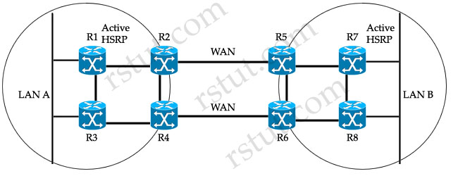
Refer to the exhibit. There are two sites connected across WAN links. All intersite and intrasite links always have the same routing metric. The network administrator sees only the top routers and links being used by hosts at both LAN A and LAN B. What would be two suggestions to load-balance the traffic across both WAN links? (Choose two)
A. Make HSRP track interfaces between the edge and core routers.
B. Replace HSRP with GLBP.
C. Add crossed intrasite links: R1-R4, R2-R3, R5-R8, and R6-R7.
D. Make R3 and R8 have lower HSRP priority than R1 and R7.
E. Replace HSRP with VRRP.
Answer: B C
Explanation
The administrator sees only the top routers (R1,R2,R5 & R7) and links being used by hosts at both LAN A and LAN B because R1 & R7 are currently active HSRP routers (notice that all the data will need to go through these routers). Next, all intersite and intrasite links have the same routing metric so these active routers will send packets to R2 or R5, not R3, R4, R6 or R8 because of the lower metric of the top routers. For example, hosts in LAN A want to send data to hosts in LAN B, they will send data to R1 -> R2 -> R5 -> R7, which has lower metric than the path R1 -> R3 -> R4 -> R6 -> R5 (or R8) -> R7.
To make the network better, we should add crossed intrasite links so that R1 & R7 can send data to both R2/R4 & R5/R6 as they have the same routing metric now -> C is correct.
Cisco Gateway Load Balancing Protocol (GLBP) differs from Cisco Hot Standby Redundancy Protocol (HSRP) and IETF RFC 3768 Virtual Router Redundancy Protocol (VRRP) in that it has the ability to load balance over multiple gateways. Like HSRP and VRRP an election occurs, but rather than a single active router winning the election, GLBP elects an Active Virtual Gateway (AVG) to assign virtual MAC addresses to each of the other GLBP routers and to assign each network host to one of the GLBP routers -> B is correct.
Note: The routers that receive this MAC address assignment are known as Active Virtual Forwarders (AVF).
Here you will find answer to IPv6 Questions
Question 1
Which of these statements best describes the major difference between an IPv4-compatible tunnel and a 6to4 tunnel?
A. An IPv4-compatible tunnel is a static tunnel, but an 6to4 tunnel is a semiautomatic tunnel.
B. The deployment of a IPv4-compatible tunnel requires a special code on the edge routers, but a 6to4 tunnel does not require any special code.
C. An IPv4-compatible tunnel is typically used only between two IPv6 domains, but a 6to4 tunnel is used to connect two or more IPv6 domains.
D. For an IPv4-compatible tunnel, the ISP assigns only IPv4 addresses for each domain, but for a 6to4 tunnel, the ISP assigns only IPv6 addresses for each domain.
Answer: C
Question 2
Which IPv6 address would you ping to determine if OSPFv3 is able to send and receive unicast packets across a link?
A. anycast address
B. site-local multicast
C. global address of the link
D. unique local address
E. link-local address
Answer: E
Question 3
You are using IPv6, and would like to configure EIGRPv3. Which three of these correctly describe how you can perform this configuration? (Choose three)
A. EIGRP for IPv6 is directly configured on the interfaces over which it runs.
B. EIGRP for IPv6 is not configured on the interfaces over which it runs, but if a user uses passive-interface configuration, EIGRP for IPv6 needs to be configured on the interface that is made passive.
C. There is a network statement configuration in EIGRP for IPv6, the same as for IPv4.
D. There is no network statement configuration in EIGRP for IPv6.
E. When a user uses a passive-interface configuration, EIGRP for IPv6 does not need to be configured on the interface that is made passive.
F. When a user uses a non-passive-interface configuration, EIGRP for IPv6 does not need to be configured on the interface that is made passive
Answer: A D E
Question 4
Which of these statements accurately identifies how Unicast Reverse Path Forwarding can be employed to prevent the use of malformed or forged IP sources addresses?
A. It is applied only on the input interface of a router.
B. If is applied only on the output interface of a router.
C. It can be configured either on the input or output interface of a router.
D. It cannot be configured on a router interface.
E. It is configured under any routing protocol process.
Answer: A
Question 5
Unicast Reverse Path Forwarding can perform all of these actions except which one?
A. examine all packets received to make sure that the source addresses and source interfaces appear in the routing table and match the interfaces where the packets were received
B. check to see if any packet received at a router interface arrives on the best return path
C. combine with a configured ACL
D. log its events, if you specify the logging options for the ACL entries used by the unicast rpf command
E. inspect IP packets encapsulated in tunnels, such as GRE
Answer: E
Question 6
During the IPv6 address resolution, a node sends a neighbor solicitation message in order to discover which of these?
A. The Layer 2 multicast address of the destination node
B. The solicited node multicast address of the destination node
C. The Layer 2 address of the destination node based on the destination IPv6 address
D. The IPv6 address of the destination node based on the destination Layer 2 address
Answer: C
Question 7
When using IP SLA FTP operation, which two FTP modes are supported? (Choose two)
A. Only the FTP PUT operation type is supported.
B. Active mode is supported.
C. Passive FTP transfer modes are supported.
D. FTP URL specified for the FTP GET operation is not supported.
Answer: B C
Here you will find answers to Multicast Questions
Question 1
In PIM-SM what control plane signaling must a multicast source perform before it begins to send multicast traffic to a group?
A. The source must send a PIM Register message to the rendezvous point (RP).
B. The source must first join the multicast group using IGMP before sending.
C. The source must perform a Request to Send (RTS) and Clear to Send (CTS) handshake with the PIM designated router (DR).
D. No control plane signaling needs to be performed; the source can simply begin sending on the local subnet.
Answer: D
Question 2
The ip pim autorp listener command is used to do which of these?
A. enable a Cisco router to “passively” listen to Auto-RP packets without the router actively sending or fotwarding any of the packets
B. allow Auto-RP packets in groups 224.0.1.39 and 224.0.1.40 to be flooded in dense mode out interfaces configured with the ip pim sparse-mode command
C. enable the use of Auto-RP on a router
D. configure the router as an Auto-RP mapping agent
Answer: B
Question 3
In order to configure two routers as anycast RPs, which of these requirements, at a minimum, must be satisfied?
A. Multicast Source Discovery Protocol mesh-groups must be configured between the two anycast RPs.
B. The RPs must be within the same IGP domain.
C. Multicast Source Discovery Protocol must be configured between the two anycast RPs.
D. The two anycast RPs must be IBGP peers.
Answer: C
Question 4
Which two of these statements correctly describe classic PIM-SM? (Choose two)
A. The IOS default is for a last-hop router to trigger a switch to the shortest path tree as soon as a new source is detected on the shared tree.
B. The IOS default is for every one of the routers on the shared tree to trigger a switch to the shortest path tree as soon as a new source is detected on the shared tree.
C. The default behavior of switching to the shortest path tree as soon as a new source is detected on the shared tree can be disabled by setting the value in the ip pim spt-threshold command to “infinity”.
D. The default behavior of switching to the shortest path tree as soon as a new source is detected on the shared tree can be disabled by setting the value in the ip pim spt-threshold command to “zero”.
Answer: A C
Question 5
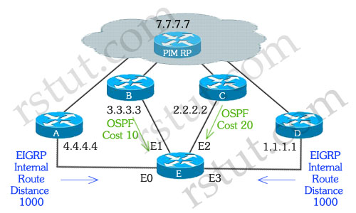
Refer to the exhibit. Router E learned about the PIM RP (designated as 7.7.7.7) from four different sources. Routers A and D advertised the 7.0.0.0 network via EIGRP. Routers B and C advertised the 7.0.0.0 network via OSPF. Considering that all four Ethernet interfaces on router E could potentially lead back to the PIM-RP, when router E receives the first multicast packet down the shared tree, which incoming interface will be used to successfully pass the RPF check?
A. E0
B. E1
C. E2
D. E3
E. None of these interfaces will be used to successfully pass the RPF check.
F. All of these interfaces would successfully pass the RPF check.
Answer: A
Question 6
Refer to the exhibit. Two ISPs have decided to use MSDP and configured routers X and Y (both are PIM RPs) as MSDP peers. In the domain of ISP B, PC A has sent an IGMP membership report for the group 224.1.1.1 and PC B has sent an IGMP membership report for the group 224.5.5.5. Assuming that the MSDP peering relationship between routers X and Y is functional, and given the partial configuration output shown from router X, which two of these statements are true? (Choose two)

A. Router X will contain an entry for 224.1.1.1 in its SA cache and will also have an installed (S,G) entry for this in its mroute table
B. Router X will not contain an entry for 224.1.1.1 in its SA cache but will have an installed (*,G) entry for this in its mroute table.
C. Router X will not contain an entry for 224.5.5.5 in its SA cache but will have an installed (S,G) entry for this in its mroute table.
D. Router X will not contain an entry for 224.5.5.5 in its SA cache but will have an installed (*,G) entry for this in its mroute table.
E. Router X will have no entries for 224.5.5.5 in neither its SA cache nor in its mroute table.
F. Router X will have no entries for 224.1.1.1 in neither its SA cache nor in its mroute table.
Answer: A D
Here you will find answers to Multicast Questions – Part 2
Question 1
Which action must be taken by a host if it wants to join a multicast group?
A. send an IGMPv2 membership report using unicast to the default router on the local subnet
B. send an IGMPv2 membership report using unicast to the rendezvous point for the group
C. send an IGMPv2 membership report using multicast to the “All-PIM-Routers” multicast group, 224.0.0.2, on the local subnet
D. send an IGMPv2 membership report using multicast on the local subnet with the destination IP address set to the multicast group being joined
Answer: D
Question 2
Which statement correctly describes Designated Forwarder in bidirectional PIM?
A. It has the best route to the rendezvous point and is the only router on the local subnet that may forward multicast traffic up the shared tree
B. It is responsible for forwarding all multicast traffic on to and off of the local subnet
C. It is elected based on the highest IP address of all PIM routers on the local subnet and is the only router on the local subnet that may forward multicast traffic up the shared tree
D. It has the best route to the rendezvous point and is the only router on the local subnet that may forward multicast traffic down the shared tree
Answer: A
Question 3
Why does the network administrator always avoid applying the multicast address 255.0.0.11 to multicast applications?
A. This Layer 3 IP multicast address is mapped to a layer 2 MAC address that will always be flooded to all ports of a Cisco Layer 2 switch
B. The address is reserved by the IANA for the Session Announcement Protocol
C. this is a link-local multicast address which is never forwarded beyond the local subnet
D. This address is reserved by the IANA for the Multicast Address Dynamic Client Allocation Protocol
Answer: A
Question 4
Refer to the following descriptions about anycast RPs. Which one is true?
A. Anycast RPs are unable to be used in conjunction with Auto-RPs
B. After a failure of one of the anycast RPs, the PIM network will reconverge on the remaining anycast RP or RPs in less than one second
C. After a failure of one of the anycast RPs, the PIM network will reconverge on the remaining anycast RP or RPs in roughly the same time that it takes unicast routing to reconverge
D. The anycast RPs should be within the same IGP domain
Answer: C
Question 5
IGMP has versions IGMP vl, v2 and v3. Which improvements does IGMPv3 offer over IGMPv2?
A. IGMPv3 added the ability for a host to specify which sources in a multicast group it wishes to receive
B. IGMPv3 added the ability for a host to specify which sources in a multicast group it does not wishes to receive
C. IGMPv3 removed the ability to perform a wildcard join of all sources in a multicast group
D. IGMPv3 removed the report-suppression feature for IGMP membership reports
Answer: A B D
Question 6
IANA is the central authority that maintains strict control on how IP addresses are used. Do you know the IP multicast addresses range it reserves for administratively scoped multicast?
A. 239.0.0.0 239.255.255.255
B. 233.0.0.0 233.255.255.255
C. 232 0.0.0 232.255.255.255
D. 224.0.0.0 224.0.0.255
Answer: A
Question 7
Each SPT (S,G) and shared tree (*,G) is defined as an entry in the multicast routing table. Once the table is built, any multicast packets received that match a specific (S,G) or (*,G) route entry will be forwarded out the outgoing interface list. Which addresses below can be used in the S entries?
A. Source Specific Multicast addresses
B. GLOP addresses
C. SDP / SAP addresses
D. any class A, class B, or class C host addresses
Answer: D
Here you will find answers to Drag and Drop Questions
Question 1
Drag the items to the proper locations

Answer:
Classification —> near the edge network
Queuing —> congestion management
Marking —> packet differentiation
RED —> drop packets
Shaping —> tail drop
Policing —> inbound interface
Explanation
Classification entails using a traffic descriptor to categorize a packet within a specific group to define that packet and make it accessible for QoS handling on the network. For example, you can use classification to mark certain packets for IP Precedence. IP Precedence is usually deployed as close to the edge of the network or the administrative domain as possible.
Queuing is designed to accommodate temporary congestion on a network device’s interface by storing excess packets in buffers until bandwidth becomes available.
When a queue is full, IOS has no place to put newly arriving packets, so it discards them. This phenomenon is called tail drop. Often, when a queue fills, several packets are tail dropped at a time, given the bursty nature of data packets.
Marking allows the QoS level of the packet to change based upon classification or policing. Tail drop is the default drop mechanism.
Traffic shaping prevents the bit rate of the packets exiting an interface from exceeding a configured shaping rate. To do so, the shaper monitors the bit rate at which data is being sent. If the configured rate is exceeded, the shaper delays packets, holding the packets in a shaping queue. The shaper then releases packets from the queue such that, over time, the overall bit rate does not exceed the shaping rate.
Random Early Detection (RED) monitors the average queue size and drops packets based on statistical probabilities. If the buffer is almost empty, all incoming packets are accepted. As the queue grows, the probability for dropping an incoming packet grows too. When the buffer is full, the probability has reached 1 and all incoming packets are dropped.
Shaping implies the existence of a queue and of sufficient memory to buffer delayed packets, while policing does not. Queuing is an outbound concept; packets going out an interface get queued and can be shaped. Only policing can be applied to inbound traffic on an interface. Ensure that you have sufficient memory when enabling shaping. In addition, shaping requires a scheduling function for later transmission of any delayed packets. This scheduling function allows you to organize the shaping queue into different queues. Examples of scheduling functions are Class Based Weighted Fair Queuing (CBWFQ) and Low Latency Queuing (LLQ).
Here you will find answers to QoS Questions
Question 1
Which of these is a valid differentiated services PHB?
A. Guaranteed PHB
B. Class-Selector PHB
C. Reserved Forwarding PHB
D. Discard Eligible PHB
E. Priority PHB
Answer: B
Question 2
Refer to the exhibit. When applying this hierarchical policy map on the on the tunned interface, you measure high jitter for traffic going through class 1234. What is the most likely cause of this jitter?
class-map match-all 1234
  match ip precedence 5
class-map match-all 5555
  match access-group 105
class-map match-all 5554
  match access-group 104

policy-map tun-shap
 class class-default
   shape average 150000 300000
   service-policy mark

policy-map mark
 class 1234
  priority 64
 class 5555
  set dscp af31
  bandwidth remaining percent 50
  random-detect  dscp-based
 class 5554
  set dscp af32
  bandwidth remaining percent 25
  random-detect dscp-based
interface Tunnel 1
 ip address 20.2.2.1  255.255.255.252
 ip load-sharing per-packet
 load-interval 30
 qos pre-classify
 tunnel source 4.4.4.1
 tunnel destination 4.4.4.2
 service-policy output tun-shap

access-list 104 permit ip any host  5.5.5.4
access-list 105 permit ip any host 5.5.5.5
A. The configuration of a hierarchical policy map on a tunnel interface is not supported.
B. Class 5555 and class 5554 are both taking up 100% of the bandwidth, leaving nothing for class 1234.
C. The burst size for the traffic shaping is wrongly configured to 15000; this would require an interface capable of sending at 150Mb/s.
D. The burst size for the traffic shaping has been wrongly configured; it should be set as low as possible.
E. The burst size for the traffic shaping has been wrongly configured; it should be set as high as possible.
Answer: D
Question 3
Refer to the exhibit. When applying this policy map on the tunnel1 interface, you see packet loss for the TCP class starting at around 100000 b/s, instead of the configured 150000 b/s. What is the most likely cause of the discrepancy?
class-map match-any tcp
 match protocol http
 match protocol ftp
class-map match-all acl180
 match access-group 180

policy-map police
 class tcp
    police 150000 1000 conform-action transmit exceed-action drop
 class acl180
    police 150000 conform-action set-prec-transmit 2 exceed-action set-prec-transmit 1 violate-action set-prec-transmit 0

interface Tunnel1
 ip address 20.1.1.2 255.255.255.252
 service-policy input police
 load-interval 30
 tunnel-source 4.4.4.2
 tunnel destination 4.4.4.1
A. The violate-action command should not be configured.
B. The current configuration of the load-interval command on the tunnel interface is preventing proper policing calculations.
C. The burst size is too low.
D. Policing on tunnel interfaces is not supported.
E. The CIR keyword is missing in the policer.
Answer: C
Question 4
Refer to the exhibit. As a network administrator, you have configured a dual-rate, dual- bucket policer in accordance with RFC 2698 on the serial interface of you router, connecting to your provider. The SLA with your provider states that you should only send AF31 (limited to 150 kb/s), AF32 (limited to 50 kb/s)and AF33 (best effort). Your service provider claims you are not conforming to the SLA Which two things are wrong with this configuration? (Choose two.)
class-map match-all af31
 match dscp af31
class-map match-all af32
 match dscp af32
class-map match-all af33
 match dscp af33

policy-map marking
 class af31
  set dscp af31
 class af32
  set dscp af32
 class af33
  set dscp af33

policy-map limit
 class af33
  police cir 150000 bc 50000 pir 200000 be 50000
   conform-action set-dscp-transmit af31
   exceed-action set-dscp-transmit af32
   violate-action set-dscp-transmit default
 class class-default
 bandwidth 300

interface Ethernet0/1
 ip address 3.3.3.1 255.255.255.0
 no ip proxy-arp
 load-interval 30
 half-duplex
 no keepalive
 no cdp enable
 service-policy input marking

interface serial0/0
 ip address 4.4.4.1 255.255.255.252
 ip load-sharing per-packet
 encapsulation ppp
 load-interval 30
 no dce-terminal-timing-enable
 service-policy output limit
A. The configuration of a service policy on half-duplex Ethernet interfaces is not supported.
B. The class class-default sub-command of the policy-map limit command should be set to the DSCP default.
C. The violate action is wrong.
D. This policer configuration is not implementing RFC 2698 dual-bucket, dual-rate.
E. The policer is configured in the wrong class
Answer: C E
Question 5
Refer to the exhibit. You have noticed that several users in the network are consuming a great deal of bandwidth for the peer-to-peer application Kazaa2. You would like to limit this traffic, and at the same time provide a guaranteed 100 kb/s bandwidth for one of your servers. After applying the configuration in the exhibit, you notice no change in the bandwidth utilization on the serial link; it is still heavily oversubscribing the interface.
What is the cause of this problem?
no ip cef
class-map match-all kazza2
 match protocol kazza2
 class-map match-all server
 match access-group 105

policy-map p2p
 class kazaa2
 drop
 class server
 bandwidth 100
 class class-default

fair-queue

interface Serial0/0
 bandwidth 1234
 ip address 20.1.34.1 255.255.255.252
 ip load-sharing per-packet
 encapsulation ppp
 load-interval 30
 no dce-terminal-timing-enable
 service-policy output p2p
A. CEF needs to be enabled for NBAR.
B. In class Kazaa2, you should configure a policer instead of a drop command.
C. The server class should have a priority of 100.
D. The bandwidth parameter on serial 0/0 is wrong.
E. Kazaa2 is not a valid protocol.
Answer: A
Question 6
All of these are fundamental building blocks of a differentiated senvices Traffic Conditioner Block except which one?
A. dropper
B. classifier
C. marker
D. querier
E. meter
F. shaper
Answer: D
Question 7
Refer to the exhibit. You would like to guarantee 7 Mb/s for FTP traffic in your LAN, as it seems that peer-to-peer traffic is taking up a large amount of bandwidth. When testing the configuration, you notice that FTP traffic doesn’t reach 7 Mb/s. What is the problem?
ip cef

class-map match-all ftp
 match protocol ftp
class-map match-all voice
 match precedence 5

policy-map mark
 class voice
 priority 200
class ftp
 set dscp af32
 bandwidth 7000
 random-detect
 dscp-based
class class-default

interface Tunnel1
 ip address 20.1.1.1 255.255.255.252
 load-interval 30
 qos pre-classify
 tunnel source 4.4.4.1
 tunnel destination 4.4.4.2
!
interface Tunnel2
 ip address 20.2.2.1 255.255.255.252
 load-interval 30
 qos pre-classify
 tunnel source 4.4.4.1
 tunnel destination 4.4.4.2

interface Ethernet0/1
 ip address 4.4.4.1 255.255.255.0
 no ip proxy-arp
 load-interval 30
 half-duplex
 no keepalive
 no cdp enable
 service-policy output mark
A. The Ethernet interface should have keepalives enabled.
B. The duplex settings are wrong on the Ethernet interface.
C. The qos pre-classify command should be removed from the tunnel interfaces.
D. the priority queue for the voice class is probably taking all the bandwidth
E. there are probably not enough interface buffers; they should be tuned.
Answer: B
Question 8
NBAR supports all of these with the exception of which one?
A. HTTP
B. IP multicast
C. TCP flows with dynamically assigned port numbers
D. non-UDP protocols
Answer: B
Explanation
NBAR classifies packets that are normally difficult to classify. For instance, some applications use dynamic port numbers. NBAR can look past the UDP and TCP header, and refer to the host name, URL, or MIME type in HTTP requests.
Question 9
Modified deficit round robin supports which of these functionalities?
A. priority queue
B. weighted fair queues
C. round-robin service of output queues
D. LLQ
Answer: A C
Question 10
A router is connected to an HDLC circuit via a T1 physical interface. The SLA for this link only allows for a sustained rate of 768 kb/s. Bursts are allowed for up to 30 seconds at up to line rate, with a window Tc of 125 ms.
What should the Be and Be setting be when using generic traffic shaping?
A. Be = 46320000 , Bc = 96000
B. Be = 768000 Bc = 32000
C. Be = 128000 Bc = 7680
D. Be = 0 Bc = 96000
Answer: A
Explanation
(Notice that the sustained rate is the CIR = 768kb/s)
From the formula Tc=Bc/CIR => Bc = Tc * CIR = 125ms * 768kb/s = 96000 bits
(In fact you should calculate with the default units, that is 0.125s * 768000b/s)
The T1 speed is 1.544 Mbps = 1544000bps. “Bursts are allowed for up to 30 seconds at up to line rate” ->Be = 1544000bps * 30 = 46320000 bits.
Terminologies: The term CIR refers to the traffic rate for a VC based on a business contract.
Tc is a static time interval, set by the shaper.
Committed burst (Bc) is the number of bits that can be sent in each Tc.
Be is the excess burst size, in bits. This is the number of bits beyond Bc that can be sent after a period of inactivity.
Question 11
Which two of these parameters are used to determine a forwarding equivalence class? (Choose two)
A. IP prefix
B. Layer 2 circuit
C. RSVP request from CE for bandwidth reservation
D. BGP MED value
Answer: A B
Recommended reading:
+ QoS Frequently Asked Questions
Here you will find answers to QoS Questions – Part 2
Question 1
What is an important consideration that should be taken into account when configuring shaped round robin?
A. It enables policing.
B. Strict priority is not supported.
C. WRED must be previously enabled.
D. It enables WRR.
Answer: B
Explanation
First we need to understand how round robin algorithm works. The round robin uses multiple queues and dispatches one packet from each queue in each round with no prioritization. For example, it dispatches:
+ Dispatch one packet from Queue 1
+ Dispatch one packet from Queue 2
+ Dispatch one packet from Queue 3
+ Repeat from Queue 1
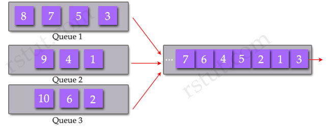
There are three implementations of Round Robin scheduling on the Catalyst 6500 and they include Weighted Round Robin (WRR), Deficit Weighted Round Robin (DWRR) and Shaped Round Robin (SRR).
The Weighted Round Robin allows prioritization, meaning that it assigns a “weight” to each queue and dispatches packets from each queue proportionally to an assigned weight. For example:
+ Dispatch 3 packets from Queue 1 (Weight 3)
+ Dispatch 2 packets from Queue 2 (Weight 2)
+ Dispatch 1 packet from Queue 1 (Weight 1)
+ Repeat from Queue 1 (dispatch 3 next packets)
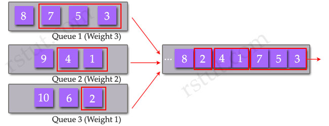
Unlike Priority Queuing, which always empties the first queue before going to the next queue, this kind of queue prevents starvation of other applications such as if a large download is in progress.
The Weighted Round Robin can be used with Strict Priority by setting its weight to 0. That means packets in the other queues will not be serviced until queue 4 is emptied.
The problem of WRR is the router is allowed to send the entire packet even if the sum of all bytes is more than the threshold and can make other applications starved.
The Deficit Round Robin solves problem of WRR by keeping track of the number of “extra” bytes dispatched in each
round – the “deficit” and then add the “deficit” to the number of bytes dispatched in the next round.
Shaped Round Robin (SRR) is scheduling service for specifying the rate at which packets are dequeued. With SRR there are two modes, shaped and shared. Shaped mode is only available on the egress queues. Shaped egress queues reserve a set of port bandwidth and then send evenly spaced packets as per the reservation. Shared egress queues are also guaranteed a configured share of bandwidth, but do not reserve the bandwidth. That is, in shared mode, if a higher priority queue is empty, instead of the servicer waiting for that reserved bandwidth to expire, the lower priority queue can take the unused bandwidth. Neither shaped SRR nor shared SRR is better than the other. Shared SRR is used to get the maximum efficiency out of a queuing system, because unused time slots can be reused by queues with excess traffic. This is not possible in a standard Weighted Round Robin. Shaped SRR is used to shape a queue or set a hard limit on how much bandwidth a queue can use. When you use shaped SRR, you can shape queues within a port’s overall shaped rate.
(Reference: http://www.cisco.com/en/US/prod/collateral/switches/ps5718/ps7078/prod_qas0900aecd805bacc7.html)
Question 2
What are the advantages of using WRED ? (Select two)
A. offers bounded low latency
B. offers minimal bandwidth guarantees
C. avoids TCP synchronization
D. allows a different drop profile to be manually enabled for each IP precedence or DSCP
Answer: C D
Explanation
Nowadays most routers have packet queues, which allow them to hold packets in their buffers during periods of congestion, rather than discarding them. However, the buffers have limited size and the queue is allowed to fill to its maximum size. If the queue is bigger than the buffer, surely some packets must be discarded; the decision is depended on which algorithm is used. One of the congest management algorithm is Random Early Discard (RED) algorithm whereby random frames are refused admission to the queue once a threshold has been exceeded. Cisco routers do not support RED but it supports the better one: WRED.
Weighted RED (WRED) is a derivative of RED whereby the frames priority values are inspected to determine which frames will be dropped. When the buffers reach set thresholds, then (typically) lower priority frames are dropped allowing the higher priority frames to enter the queue.
The difference between RED and WRED is that WRED can selectively discard lower-priority traffic when the interface begins to get congested. In WRED, a queue may have several different queue thresholds. By default, WRED uses a different RED profile for each weight. Each queue threshold is associated to a particular IP precedence or DSCP. For example, a queue may have lower thresholds for lower priority packet so that it drops less important packets more aggressively than important packets during periods of congestion -> D is correct.
Now let’s talk about global synchronization!
TCP has automatic recovery from dropped packets (usually when the network is congested). The sender reduces its sending rate for a certain amount of time, and then tries to find out if the network is no longer congested by increasing the rate again. This is known as the slow-start algorithm.
Almost all the senders will use the same time delay before increasing their rates. When these delays expire, at the same time, all the senders will send additional packets, the router queue will again overflow and packets will be dropped, the senders will all back off for a fixed delay… This pattern of each sender decreasing and increasing transmission rates at the same time as other senders is referred to as “global synchronization” or “TCP synchronization” and leads to inefficient use of bandwidth, due to the large numbers of dropped packets, which must be retransmitted.
WRED reduces the chances of tail drop (used by TCP) by selectively dropping packets when the output interface begins to show signs of congestion. By dropping some packets early rather than waiting until the queue is full, WRED avoids dropping large numbers of packets at once and minimizes the chances of global synchronization. Thus, WRED allows the transmission line to be used fully at all times -> C is correct.
Note: Tail drop is the simplest technique to limit queue size. When the queue is full, it simply discards any new packets until there is space in the queue again.
Question 3
WRED is a congestion avoidance mechanism. In what situation is WRED most useful?
A. most traffic is TCP-based
B. very high bandwidth interfaces such as Gigabit Ethernet
C. an equal distribution of TCP and UDP traffic
D. a mix of TCP.UDP, and non-IP traffic
Answer: A
Question 4
Refer to the exhibit. Based on this configuration, what type of marker is achieved?
policy-map QoSPolicer
   class PolicedTraffic
     police cir 512000 pir 1024000
       conform-action transmit
       exceed-action set-dscp-transmit csl
       violate-action drop
A. Single-rate, two-color marker
B. Three-rate, two-color marker
C. Two-rate, three-color marker
D. Single-rate, three-color marker
Answer: C
Question 5
Refer to the exhibit. Based on the configuration shown, which queuing mechanism has been configured on interface serial 1/0?
RouterC#show policy-map interface serial 1/0
  Serial1/0

    Service-policy output: BW-Assignment

        Class-map: VoIP (match-all)
            0 packets, 0 bytes
            5 minute offered rate 0 bps, drop rate 0 bps
            Match: protocol rtp audio
            Queueing
                 Output Queue: Conversation 265
                 Bandwidth 50 (%)
                 Bandwidth 772 (kbps) Max Threshold 64 (packets)
                 (pkts matched/bytes matched) 0/0
                 (depth/total drops/no-buffer drops) 0/0/0

        Class-map: FTP-Data (match-all)
            0 packets, 0 bytes
            5 minute offered rate 0 bps, drop rate 0 bps
            Match: access-group name FTP-Data
            Queueing
                 Output Queue: Conversation 266
                 Bandwidth 10 (%)
                 Bandwidth 154 (kbps) Max Threshold 64 (packets)
                 (pkts matched/bytes matched) 0/0
                 (depth/total drops/no-buffer drops) 0/0/0

        Class-map: class-default (match-any)
            4 packets, 954 bytes
            5 minute offered rate 0 bps, drop rate 0 bps
            Match: any
RouterC#
A. PQ
B. CQ
C. WFQ
D. LLQ
E. CBWFQ
Answer: E
Here you will find answers to Voice Questions
Question 1
Refer to the exhibit. Voice traffic is marked “precedence 5.” How much bandwidth is allocated for voice traffic during periods of congestion?
| ! class-map match-all Signal match ip precedence 3 class-map match-any System match access-group name Security match ip precedence 6 match ip precedence 7 class-map match-all Bearer match ip precedence 5 ! ! policy-map ProviderOut class Bearer priority 48 class Signal bandwidth 15 class System bandwidth 15 class class-default fair-queue random-detect shape average 512000 ! interface Ethernet0/1 description Provider Interface ip address dhcp client-id Ethernet0/1 ip access-group 111 in ip nat outside full-duplex no cdp enable service-policy output ProviderOut ! |
A. a minimum of 48 kb/s
B. a maximum of 48 kb/s
C. a minimum of 48% of the available bandwidth
D. a maximum of 48% of the available bandwidth
Answer: B
Question 2
Refer to the exhibit. Which of these is applied to the Bearer class?
| ! class-map match-all Signal match ip precedence 3 class-map match-any System match access-group name Security match ip precedence 6 match ip precedence 7 class-map match-all Bearer match ip precedence 5 ! ! policy-map ProviderOut class Bearer priority 48 class Signal bandwidth 15 class System bandwidth 15 class class-default fair-queue random-detect shape average 512000 ! interface Ethernet0/1 description Provider Interface ip address dhcp client-id Ethernet0/1 ip access-group 111 in ip nat outside full-duplex no cdp enable service-policy output ProviderOut ! |
A. WRED
B. traffic shaping
C. packet marking
D. packet classification
E. FIFO queuing within the class
Answer: E
Question 3
What is the overall type of queuing being used on the outgoing data for interface Ethernet0/1?
| ! class-map match-all Signal match ip precedence 3 class-map match-any System match access-group name Security match ip precedence 6 match ip precedence 7 class-map match-all Bearer match ip precedence 5 ! ! policy-map ProviderOut class Bearer priority 48 class Signal bandwidth 15 class System bandwidth 15 class class-default fair-queue random-detect shape average 512000 ! interface Ethernet0/1 description Provider Interface ip address dhcp client-id Ethernet0/1 ip access-group 111 in ip nat outside full-duplex no cdp enable service-policy output ProviderOut ! |
A. LLQ
B. FIFO
C. CBWFQ
D. priority queuing
E. weighted fair queuing
F. IP RTP priority queuing
Answer: A
Question 4
An expanding company is deploying leased lines between its main site and two remote sites. The bandwidth of the leased lines is 128kb/s each, terminated on different serial interfaces on the main router. These links are used for combined VOIP and data traffic. The network administrator has implemented a VOIP solution to reduce costs, and has therefore reserved sufficient bandwidth in a low latency queue on each interface for the VOIP traffic. Users now complain about bad voice quality although no drops are observed in the low latency queue. What action will likely fix this problem?
A. mark VOIP traffic with IP precedence 6 and configure only “fair-queue’ on the links
B. configure the scheduler allocate 3000 1000 command to allow the QoS code to have enough CPU cycles
C. enable class-based traffic shaping on the VoIP traffic class
D. enable Layer 2 fragmentation and interleaving on the links
E. enable Frame Relay on the links and send voice and data on different Frame Relay PVCs
Answer: D
Question 5
You are the network administrator of an enterprise with a main site and multiple remote sites. Your network carries both VOIP and data traffic. You agree with your service provider to classify VOIP and data traffic according to the different service RFCs. How can your data and VOIP traffic be marked?
A. data marked with DSCP AF21, VOIP marked with DSCP EF
B. data marked with DSCP AF51, VOIP marked with DSCP EF
C. data marked with the DE-bit, VOIP marked with the CLP-bit
D. data marked with DSCP EF, VOIP marked with DSCP AF31
E. data marked with IP precedence 5, VOIP marked with DSCP EF
Answer: A
Here you will find answers to IP Routing Questions
Question 1
Refer to the exhibit. In this network, R1 has been configured to advertise a summary route, 192.168.0.0/22, to R2. R2 has been configured to advertise a summary route. 192.168.0.0/21. to R1. Both routers have been configured to remove the discard route (the route to null created when a summary route is configured) by setting the administrative distance of the discard route to 255.

What will happen if R1 receives a packet destined to 192.168.3.1?
A. The packet will loop between R1 and R2
B. It is not possible to set the administrative distance on a summary to 255
C. The packet will be forwarded to R2, where it will be routed to null0
D. The packet will be dropped by R1, since there is no route to 192.168.3.1.
Answer: A
Question 2
While troubleshooting a network, you need to verify the liveness of hosts in the subnet 192.168.1.64/26. All of the hosts are able to reply to ping requests. How would you confirm the existing nodes using one single command?
A. ping 192.168.1.255
B. ping with sweep option
C. ping 192.168.1.127
D. ping 192.168.1.64
E. ping with broadcast option
Answer: C
Explanation
The 192.168.1.27 is the broadcast address of the 192.168.1.64/26 sub-network so by sending a ping request to this address all the hosts in this subnet will reply (to the broadcast address). But it is not quite right nowadays as all the Cisco’s routers which have IOS version 12.0 or above will simply drop these pings. If you wish to test this function then you have to turn on the “ip directed-broadcast” function (which is disabled by default from version 12.0).
The purpose of the “ip directed-broadcast” command is to enable forwarding of directed broadcasts. When this is turned on for an interface, the interface will respond to broadcast messages that are sent to its subnet. Cisco introduced this command in IOS version 10 (and it is enabled by default) but they soon realized this command was being exploited in denial of service attacks and disabled it from version 12.0.
As you can guess, a ping to the broadcast address requires all hosts in that subnet to reply and it consumes much traffic if many are sent. A type of this attack is “smurf attack”, in which the attacker tries to borrow the victim’s IP address as the source address and sends ICMP packets to the broadcast address of the network. When all the hosts in that subnet hear the ICMP request, they will reply to the computer which the attacker borrowed the IP address from.
You can try this function by enabling “ip directed-broadcast” command in interface mode. Then from the directly connected router issue the ping to the broadcast address of that subnet (or ping 255.255.255.255).
Question 3
Which mechanism can you use to achieve sub-second failover for link failure detection when a switched Ethernet media is used and loss of signal is not supported by the link provider?
A. OSPF standard hellos
B. Cisco Discovery Protocol link detection
C. Bidirectional Forwarding Detection
D. Fast Link Pulse
E. autonegotiation
Answer: C
Explanation
BFD is a detection protocol designed to provide fast forwarding path failure detection times for all media types, encapsulations, topologies, and routing protocols. In addition to fast forwarding path failure detection, BFD provides a consistent failure detection method for network administrators. Because the network administrator can use BFD to detect forwarding path failures at a uniform rate, rather than the variable rates for different routing protocol hello mechanisms, network profiling and planning will be easier, and reconvergence time will be consistent and predictable
(Reference: http://www.cisco.com/en/US/docs/ios/12_0s/feature/guide/fs_bfd.html)
Question 4
Half of your network uses RIPv2 and the other half runs OSPF. The networks do not communicate with each other. Which two of these factors describe the impact of activating EIGRP over each separate part? (Choose two)
A. EIGRP will not be accepted when configured on the actual RIPv2 routers.
B. OSPF will no longer be used in the routing table, because you only have EIGRP internal routes running.
C. OSPF will no longer be used in the routing table, because you only have EIGRP external routes running.
D. RIPv2 will populate its RIP database but not its routing table, because you only have EIGRP external routes running.
E. RIPv2 will populate its RIP database but not its routing table, because you only have EIGRP internal routes running.
F. OSPF database will have RIPv2 routes.
Answer: B E
Question 4
Based on the exhibit presented. What will be the objective of this route map when applied to traffic passing through a router?
| route-map direct-traffic permit 10 match ip address 100 set next-hop 10.1.1.1 ……………. access-list 100 permit ip any host 10.1.14.25 access-list 100 permit ip 10.2.0.0 0.0.255.255 any |
A. Take any packet sourced from any address in the 10.2.0.0/16 network or destined to 10.1.14.25 and set the next hop to 10.1.1.1
B. Take any packet sourced from any address in the 10.2.0.0/16 network and destined to 10.1.14.25 and set the next hop to 10.1.1.1
C. Nothing; extended access lists are not allowed in route maps used for policy-based routing
D. Drop any packet sourced from 10.2.0.0/16
Answer: A
Here you will find answers to MPLS Questions
Question 1
Which statement correctly describes the disabling of IP TTL propagation in an MPLS network?
A. The TTL field from the IP packet is copied into the TTL field of the MPLS label header at the ingress edge LSR.
B. TTL propagation cannot be disabled in an MPLS domain.
C. TTL propagation is only disabled on the ingress edge LSR.
D. The TTL field of the MPLS label header is set to 255.
E. The TTL field of the IP packet is set to 0.
Answer: D
Explanation
Time-to-Live (TTL) is a 8-bit field in the MPLS label header which has the same function in loop detection of the IP TTL field. Recall that the TTL value is an integer from 0 to 255 that is decremented by one every time the packet transits a router. If the TTL value of an IP packet becomes zero, the router discards the IP packet, and an ICMP message stating that the “TTL expired in transit” is sent to the source IP address of the IP packet. This mechanism prevents an IP packet from being routed continuously in case of a routing loop.
By default, the TTL propagation is enabled so a user can use “traceroute” command to view all of the hops in the network.
We can disable MPLS TTL propagation with the “no mpls ip propagate-ttl” command under global configuration. When entering a label-switched path (LSP), the edge router will use a fixed TTL value (255) for the first label. This increases the security of your MPLS network by hiding provider network from customers.
Question 2
Which three of these statements about penultimate hop popping are true? (Choose three)
A. It is used only for directly connected subnets or aggregate routes.
B. It can only be used with LDP.
C. It is only used when two or more labels are stacked.
D. It enables the Edge LSR to request a label pop operation from its upstream neighbors.
E. It is requested through TDP using a special label value that is also called the implicit-null value.
F. It is requested through LDP using a special label value that is also called the implicit- null value.
Answer: A D F
Question 3
Which of these tables is used by an LSR to perform a forwarding lookup for a packet destined to an address within an RFC 4364 VPN?
A. CEF
B. FIB
C. LFIB
D. IGP
Answer: C
Explanation
(Notice: The term Label Switch Router (LSR) refers to any router that has awareness of MPLS labels)
Label Forwarding Information Base (LFIB) is responsible for forwarding incoming packets based on label as it holds necessary label information, as well as the outgoing interface and next-hop information.
Question 4
A network is composed of several VRFs. It is required that VRF users VRF_A and VRF_B be able to route to and from VRF_C, which hosts shared services. However, traffic must not be allowed to flow between VRF_A and VRF_B. How can this be accomplished?
A. route redistribution
B. import and export using route descriptors
C. import and export using route targets
D. Cisco MPLS Traffic Engineering
Answer: C
Question 5
Multi Protocol Label Switching (MPLS) is a data-carrying mechanism that belongs to the family of packet-switched networks. For an MPLS label, if the stack bit is set to 1, which option is true?
A. The stack bit will only be used when LDP is the label distribution protocol
B. The label is the last entry in the label stack.
C. The stack bit is for Cisco implementations exclusively and will only be used when TDP is the label distribution protocol.
D. The stack bit is reserved for future use.
Answer: B
Explanation

MPLS Header Packet Format
LABEL: 20 bits
EXP: Experimental, 3bits – are reserved for experimental use
S: Bottom of stack, 1 bit
TTL: Time to Live, 8bits – same as IP TTL
The bottom-of-stack bit, or “stack bit”, is just used to indicate it is the bottom of the label stack because it is possible (and common) to have more than one label attached to a packet. The bottommost label in a stack has the S bit set to 1, other labels have the S bit set to 0. Sometimes it is useful to know where the bottom of the label stack is and the S bit is the tool to find it.
Here you will find answers to Security Questions
Question 1
Which of these is mandatory when configuring Cisco IOS Firewall?
A. Cisco IOS IPS enabled on the untrusted interface
B. NBAR enabled to perform protocol discovery and deep packet inspection
C. a route map to define the trusted outgoing traffic
D. a route map to define the application inspection rules
E. an inbound extended ACL applied to the untrusted interface
Answer: E
Question 2
If a certificate authority trustpoint is not configured when enabling HTTPS and the remote HTTPS server requires client authentication, connections to the secure HTTP client will fail. Which command must be enabled for correct operation?
A. ip http client secure-ciphersuite 3des-ede-cbc-sha
B. ip https max-connections 10
C. ip http timeout-policy idle 30 life 120 requests 100
D. ip http client secure-trustpoint trustpoint-name
Answer: D
Question 3
Which two of these elements need to be configured prior to enabling SSH? (Choose two)
A. hostname
B. loopback address
C. default gateway
D. domain name
E. SSH peer address
Answer: A D
Explanation
A hostname and a domain name were required to generate the keys, since router uses its fully qualified domain name (FQDN) as the label of the key pair.
A fully qualified domain name (FQDN) is the complete domain name for a specific computer, or host, on the Internet. The FQDN consists of two parts: the hostname and the domain name. For example, an FQDN for a mail server might be myemail.rstut.com. The hostname is “myemail”, and the host is located within the domain “rstut.com”.
Set a host name
hostname myemail
Set a ip domain name
ip domain-name rstut.com
Question 4
Spoofing attack is increasingly more common and becoming more sophisticated. Which Cisco IOS feature can provide protection against spoofing attacks?
A. lock-any-key ACL and/or reflexive ACL
B. TCP Intercept
C. IP Source Guard and/or Unicast RPF
D. Cisco IOS Firewall (CBAC)
Answer: C
Explanation
IP spoofing is a situation in which an intruder uses the IP address of a trusted device in order to gain access to your network.
IP Source Guard tracks the IP addresses of the host connected to each port and prevents traffic sourced from another IP address from entering that port. The tracking can be done based on just an IP address or on both IP and MAC addresses.
The Unicast Reverse Path Forwarding feature (Unicast RPF) helps the network guard against “spoofed” IP packets passing through a router. A spoofed IP address is one that is manipulated to have a forged IP source address. Unicast RPF enables the administrator to drop packets that lack a verifiable source IP address at the router. Note how similar this is to the Reverse Path Forwarding check with multicast traffic. In that case, traffic was dropped to avoid loops.
Question 5
Which is the result of enabling IP Source Guard on an untrusted switch port that does not have DHCP snooping enabled?
A. DHCP requests will be switched in the software, which may result in lengthy response times.
B. The switch will run out of ACL hardware resources.
C. All DHCP requests will pass through the switch untested.
D. The DHCP server reply will be dropped and the client will not be able to obtain an IP address.
Answer: D
Explanation
DHCP snooping is a feature that provides network security by filtering untrusted DHCP messages and by building and
maintaining a DHCP snooping binding database. DHCP snooping acts like a firewall between untrusted hosts and DHCP servers. DHCP snooping allows all DHCP messages on trusted ports, but it filters DHCP messages on untrusted ports.
Let’s see an example without DHCP snooping.
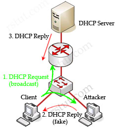
In this example, a client is trying to get a valid IP address from the DHCP Server. It sends out a DHCP Request (broadcast) message so both the DHCP Server and the Attacker can hear it. The attacker pretends to be a DHCP Server and replies to the request with a valid IP address but using its own IP address as the default gateway. If its reply can arrive before the real DHCP reply, it will be considered the default gateway. From now, the client will send packets to the attacker as it believes the attacker is the default gateway. The attacker captures these packets and sends a copy to the desired default gateway -> it becomes a “man in the middle”.
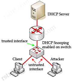
Cisco switches can use DHCP snooping feature to mitigate this type of attack. When DHCP snooping is enabled, switch ports are classified as trusted or untrusted. Trusted ports are allowed to send all types of DHCP messages while untrusted ports can send only DHCP requests. If a DHCP reply is seen on an untrusted port, the port is shut down.
By default, if you enable IP source guard without any DHCP snooping bindings on the port, a default port access-list (PACL) that denies all IP traffic expect the DHCP Request (DHCP Discover) is installed on the port. Therefore the DHCP Server can hear the DHCP Request from the Client but its reply is filtered by the switch and the client can’t obtain an IP address -> D is correct.
Some useful information about DHCP snooping & IP Source Guard:
When enabled along with DHCP snooping, IP Source Guard checks both the source IP and source MAC addresses against the DHCP snooping binding database (or a static IP source entry). If the entries do not match, the frame is filtered. For example, assume that the show ip dhcp snooping binding command displays the following binding table entry:
| MacAddress | IpAddress | LeaseSec | Type | VLAN | Interface |
| 01:25:4A:5E:6D:25 | 10.0.0.20 | 6943 | dhcp-snooping | 2 | FastEthernet0/1 |
If the switch receives an IP packet with an IP address of 10.0.0.20, IP Source Guard forwards the packet only if the MAC address of the packet is 01:25:4A:5E:6D:25.
Here you will find answers to Access list Questions
Question 1
What is the purpose of an explicit “deny any” statement at the end of an ACL?
A. none, since it is implicit
B. to enable Cisco IOS IPS to work properly; however, it is the deny all traffic entry that is actually required
C. to enable Cisco IOS Firewall to work properly; however, it is the deny all traffic entry that is actually required
D. to allow the log option to be used to log any matches
E. to prevent sync flood attacks
F. to prevent half-opened TCP connections
Answer: D
Explanation
As we know, there is always a “deny all” line at the end of each access-list to drop all other traffic that doesn’t match any “permit” lines. You can enter your own explicit deny with the “log” keyword to see what are actually blocked , like this:
Router(config)# access-list 1 permit 192.168.30.0 0.0.0.255
Router(config)# access-list 1 deny any log
Note: The log keyword can be used to provide additional detail about source and destinations for a given protocol. Although this keyword provides valuable insight into the details of ACL hits, excessive hits to an ACL entry that uses the log keyword increase CPU utilization. The performance impact associated with logging varies by platform. Also, using the log keyword disables Cisco Express Forwarding (CEF) switching for packets that match the access-list statement. Those packets are fast switched instead.
Question 2
A request arrived on your MPLS-vpn-bgp group. Due to a security breach, your customer is experiencing DoS attacks coming from specific subnets (200.0.10.0/24, 200.0.12.0/24). You have checked all MPLS- EBGP routes being advertised to BHK from other VPN sites and found four subnets listed:
200.0.10.0/24, 200.0.11.0/24, 200.0.12.0/24, 200.0.13.0/24. You immediately apply an outbound ACL filter using the appropriate MPLS-EBGP tool:
access-list 1 deny 0.0.0.0 255.255.254.255
access-list 1 permit any
What happens when you apply this ACL on the MPLS-EBGP connection to BHK?
A. It blocks all routes.
B. It blocks the routes 200.0.12.0/24, 200.0.10.0/24 only.
C. It blocks the routes 200.0.12.0/24, 200.0.13.0/24 only.
D. It blocks the routes 200.0.10.0/24, 200.0.13.0/24 only.
E. Nothing happens, no routes are blocked.
Answer: B
Explanation
Remember, for the wild card mask, 1’s are I DON’T CARE, and 0’s are I CARE.
In the access-list we put an 0.0.0.0 255.255.254.255 network; of course 255 means “1111 1111”. This means we don’t care about any of the bits in the first, second & 4th octets. In fact, the number 0 (in 0.0.0.0) is just smallest numbers we can throw there and it is easy to type but we can use any number, it wouldn’t matter, since I DON’T CARE about them except the third octet as the wild card mask is not all “255”.
Now let’s extract the 0 in the third octet in binary form (so easy, right?)
0 = 0000 0000
With the 254 in the wildcard mask, we only care about the last bit of the third octet because 254 is “1111 1110”. That means, if the third octet is in the form of xxxx xxx0 then it will match my access-list (x can be 0 or 1 because I DON’T CARE).
Now let’s write the third octet of 4 above subnets in binary form:
10 = 0000.1010
11 = 0000.1011
12 = 0000.1100
13 = 0000.1101
So, only 10 & 12 satisfy my access list -> I will only block the routes to 200.0.12.0/24, 200.0.10.0/24 -> B is correct.
Question 3
Your company wants to install Cisco IOS Firewall to ensure network availability and the security of your company’s resources. Refer to the following descriptions about its configuration, which three are correct? (Select three)
A. An IP inspection rule can be applied in the inbound direction on a secured interfaces
B. An IP inspection rule can be applied in the outbound direction on an unsecured interfaces
C. An ACL that is applied in the outbound direction on an unsecured interface must be an extended ACL
D. An ACL that is applied in the inbound direction on an unsecured interface must be an extended ACL
Answer: A B D
Question 4
What keywords do you need to the access-list to provide to the logging message like source address and source mac address?
A. Log
B. Log-input
C. Log-output
D. Logging
Answer: B
Explanation
The log-input option enables logging of the ingress interface and source MAC address in addition to the packet’s source and destination IP addresses and ports. Below is an example of the “log-input” option.
| *May 1 22:33:38.799: %SEC-6-IPACCESSLOGP: list ACL-IPv4-E0/0-IN permitted tcp 192.168.1.3(1025) (Ethernet0/0 000e.9b5a.9839) -> 192.168.2.1(22), 1 packet *May 1 22:39:15.075: %SEC-6-IPACCESSLOGP: list ACL-IPv4-E0/0-IN permitted tcp 192.168.1.3(1025) (Ethernet0/0 000e.9b5a.9839) -> 192.168.2.1(22), 9 packets |
(Reference: http://www.cisco.com/web/about/security/intelligence/acl-logging.html)
Here you will find answers to Switching Basics Questions
Question 1
What two features in Cisco switches help prevent Layer 2 loops? (Choose two)
A. UniDirectional Link Detection
B. Hot Standby Router Protocol
C. Virtual Router Redundancy Protocol
D. PortFast
E. root guard
F. loop guard
Answer: A F
Explanation
Both UniDirectional Link Detection (UDLD) and Loop Guard protect a switch trunk port from causing loops. Both features prevent switch ports from errantly moving from a blocking to a forwarding state when a unidirectional link exists in the network.
Unidirectional links are simply links for which one of the two transmission paths on the link has failed, but not both. This can happen as a result of miscabling, cutting one fiber cable, unplugging one fiber, GBIC problems, or other reasons
UDLD – Uses Layer 2 messaging to decide when a switch can no longer receive frames from a neighbor. The switch whose transmit interface did not fail is placed into an err-disabled state.
Loop Guard – When normal BPDUs are no longer received, the port does not go through normal STP convergence, but rather falls into an STP loop-inconsistent state.
(Reference: CCIE Routing and Switching Exam Certification Guide)
Question 2
Refer to the exhibit. Which switching feature is being tested?
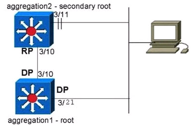
aggregation-2 (enable) set spantree portfast 3/11 ena
Waning Spantree port fast start should only be enabled on ports connected to a single host.
Connecting hubs, concentrators, switches, bridges, etc. to a fast start port can cause temporary spannmg tree loops. Use with caution.
Spantree port 3/11 fast start enabled.
aggregation-2 (enable) set spantree portfast bpdu-filter ena
Spantree portfast bpdu-filter enabled on this switch.
2001 Feb 06 13:32:14 %SPANTREE-4-LOOPGUARDBLOCK: No BPDUs were received on port 3/21 m VLAN 99. Moved to loop inconsistent state
A. loop guard
B. PortFast
C. root guard
D. BDPU guard
Answer: A
Question 3
Which three of these statements about Dynamic Trunking Protocol are correct? (Choose three)
A. It supports autonegotiation for both ISL and IEEE 802.1 Q trunks.
B. It must be disabled on an interface if you do not want the interface to work as a trunk or start negotiation to become a trunk.
C. It is a point-to-multipoint protocol.
D. It is a point-to-point protocol.
E. It is not supported on private VLAN ports or tunneling ports.
Answer: A B D
Question 4
You are designing your network to be able to use trunks. As part of this process you are comparing the ISL and 802.1 Q encapsulation options. All of these statements about the two encapsulation options are correct except which one?
A. Both support normal and extended VLAN ranges.
B. ISL is a Cisco proprietary encapsulation method and 802.1 Q is an IEEE standard.
C. ISL encapsulates the original frame.
D. Both support native VLANs.
E. 802.1 Q does not encapsulate the original frame.
Answer: D
Question 5
Refer to the exhibit. From the MAC addresses shown in the command output, to which two ports is the multicast stream 225.230.57.199 being forwarded on this switch? (Choose two)
Switch#show mac-address-table multicast
| vlan | mac address | type | ports |
| —————–+ | ——————————+ | ———————+ | —————————————————————– |
| 2 2 2 3 3 |
0100.5ee6.39c7 0100.5e00.0123 0100.5e66.39c7 0100.5e00.017f 0100.5e50.4453 |
igmp igmp igmp igmp igmp |
Gi3/7,Fa6/28,Fa7/20 Fa5/7,Fa6/28,Fa7/20 Gi3/4,Gi3/7,Fa4/10,Fa4/14,Fa7/31,Fa7/40 Gi3/7,Fa6/21 Gi3/7,Fa4/2,Fa4/3,Fa4/14,Fa4/38,Fa5/3 |
A. Fa6/28
B. Fa7/20
C. Gi3/7
D. Fa4/2
E. Fa4/14
F. Fa4/38
G. Fa6/28
H. Fa5/7
Answer: C E
Question 6
You are about to migrate a customer network to use a VSS. Which of these statements is true about a VSS?
A. The VSS switch must be the root bridge for all VLANs and is automatically designated.
B. The VSS switch is defined in RFC 4318 as a managed object.
C. The PAgP+ or LACP protocols are used to maintain the operational state of the VSS devices.
D. A VSS interoperates with a virtual port channel.
E. The 802.1Q or ISL protocols are used to maintain the operational state of the VSS devices.
F. A VSS increases the size of the spanning-tree domain.
Answer: C
Explanation
Virtual switching system (VSS) is a network system virtualization technology that pools multiple Cisco Catalyst 6500 Series Switches into one virtual switch, increasing operational efficiency, boosting nonstop communications, and scaling system bandwidth capacity to 1.4 Tbps. At the initial phase, a VSS will allow two physical Cisco Catalyst 6500 Series Switches to operate as a single logical virtual switch called a virtual switching system 1440 (VSS1440)

Virtual Switching System 1440 Compared to Traditional Network Design
(Reference: http://www.cisco.com/en/US/products/ps9336/products_tech_note09186a0080a7c837.shtml)
C is the correct answer as in the recommendations of the above link, the author wrote:
Do not use on and off options with PAgP or LACP or Trunk protocol negotiation.
* PAgP — Run Desirable-Desirable with MEC links.
* LACP — Run Active-Active with MEC links.
* Trunk — Run Desirable-Desirable with MEC links.
Recommended link: http://www.cisco.com/en/US/prod/collateral/switches/ps5718/ps9336/prod_qas0900aecd806ed74b.html
Question 7
An 802.1 Q trunk is not coming up between two switches. The ports on both switches are configured as “switchport mode desirable.” Assuming that there is no physical issue, choose two possible causes. (Choose two.)
A. Incorrect VTP domain
B. Incorrect VTP password
C. Incorrect VTP mode
D. Incorrect VTP configuration revision
Answer: A B
Question 8
Refer to the exhibit. Look at the command output. Assume that there is no other path, and the configuration is correct. What would be the consequences of this situation?
Switch1#show cdp neighbor
Capability Codes: R – Router, T- Trans Bridge, B – Source Route Bridge S – Switch, H – Host, I – IGMP, r- Repeater, P – Phone
| Device ID | Local Intrfce | Holdtme | Capability | Platform | Port ID |
| Switch2 | Gig 1/0/3 | 160 | S I | WS-C2955C | Fas0/13 |
Switch2#show cdp neighbor
Capability Codes: R – Router, T- Trans Bridge, B – Source Route Bridge S – Switch, H – Host, I – IGMP, r- Repeater, P – Phone
| Device ID | Local Intrfce | Holdtme | Capability | Platform | Port ID |
| Switch1 | Fas0/13 | 173 | R S I | WS-C3750G | Gig1/0/4 |
A. Users in SW1 can ping SW2 but not vice versa.
B. Users in SW2 can ping SW1 but not vice versa.
C. Users in SW1 and SW2 can ping each other.
D. Users in SW1 and SW2 cannot ping each other.
Answer: D
Question 9
Refer to the exhibit. Look at the command output. What can you use to prevent this behavior?
Switch 1#show cdp neighbors
Capability Codes: R – Router, T – Trans Bridge, B – Source Route Bridge S – Switch, H – Host, I – IGMP, r – Repeater
| Device ID | Local Intrfce | Holdtme | Capability | Platform | Port ID |
| Switch2 | Gig 1/0/3 | 160 | S I | WS-C2955C | Fas0/13 |
Switch 1#
Switch2#show cdp neighbor
Capability Codes: R – Router, T- Trans Bridge, B – Source Route Bridge S – Switch, H – Host, I – IGMP, r- Repeater
| Device ID | Local Intrfce | Holdtme | Capability | Platform | Port ID |
| Switch1 | Fas0/13 | 173 | R S I | WS-C3750G | Gig1/0/4 |
A. UDLD
B. spanning-tree loopguard
C. VTP mode transparent
D. switchport mode desirable
Answer: A
Here you will find answers to Spanning Tree Protocol Questions
Question 1
Spanning Tree Protocol IEEE 802.1s defines the ability to deploy which of these?
A. one global STP instance for all VLANs
B. one STP instance for each VLAN
C. one STP instance per set of VLANs
D. one STP instance per set of bridges
Answer: C
Explanation
The IEEE 802.1s standard is the Multiple Spanning Tree (MST). With MST, you can group VLANs and run one instance of Spanning Tree for a group of VLANs.
Other STP types:
+ Common Spanning Tree (CST), which is defined with IEEE 802.1Q, defines one spanning tree instance for all VLANs.
+ Rapid Spanning Tree (RSTP), which is defined with 802.1w, is used to speed up STP convergence. Switch ports exchange an explicit handshake when they transition to forwarding.
Question 2
Which two of these are used in the selection of a root bridge in a network utilizing Spanning Tree Protocol IEEE 802.1 D? (Choose two)
A. Designated Root Cost
B. bridge ID priority
C. max age
D. bridge ID MAC address
E. Designated Root Priority
F. forward delay
Answer: B D
Explanation
The IEEE 802.1 standard (STP) is used to create a loop-free Layer 2 network. This protocol uses the bridge ID (a field inside BPDU packets) to elect root bridge. It is 8 bytes in length. The first two bytes are the Bridge Priority, which is an integer in the range of 0 – 65,535 (default is 32,768). The last six bytes are a MAC address supplied by the switch.
In STP, lower bridge ID values are preferred. To compare two bridge IDs, the priority is compared first. If two bridges have equal priority, then the MAC addresses are compared. For example, if switch A (MAC=0600.0000.1111) and B (MAC=0600.0000.2222) both have a priority of 10, then switch A will be selected as the root bridge because it has lower MAC.
Question 3
If a port configured with STP loop guard stops receiving BPDUs, the port will be put into which state?
A. learning state
B. listening state
C. forwarding state
D. loop-inconsistent state
Answer: D
Explanation
Loop Guard protects a switch trunk port from causing loops. It prevents switch ports from wrongly moving from a blocking to a forwarding state when a unidirectional link exists in the network.
Unidirectional links are simply links for which one of the two transmission paths on the link has failed, but not both. This can happen as a result of miscabling, cutting one fiber cable, unplugging one fiber or other reasons.
Let’s consider an example.
The network consists of 3 switches without Loop Guard feature. Switch 1 is the root switch. A port on Switch 3 is in blocking state, other ports are forwarding normally.
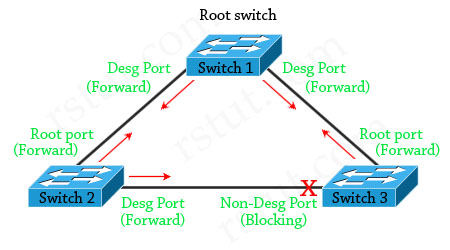
Suppose that Switch 3 does not receive BPDUs (Hellos) from Switch 2 due to unidirectional link failure on the link between switch 2 and switch 3. Switch 3 then transitions to forwarding state, and now all trunks on all switches are forwarding. Well, we have a loop!
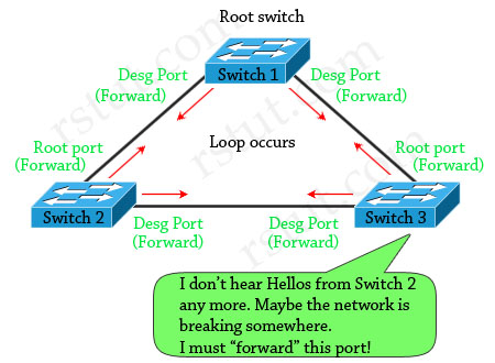
With Loop Guard feature turned on, the blocking port on switch 3 will not transition to forwarding state but will fall into an STP loop-inconsistent state (same as blocking state).
(Reference: http://www.cisco.com/en/US/tech/tk389/tk621/technologies_tech_note09186a0080094640.shtml & CCIE Routing and Switching Official Exam Certification)
Question 4
What is the purpose of the STP PortFast BPDU guard feature?
A. enforce the placement of the root bridge in the network
B. ensure that a port is transitioned to a forwarding state quickly if a BPDU is received
C. enforce the borders of an STP domain
D. ensure that any BPDUs received are forwarded into the STP domain
Answer: C
Explanation
By default, STP runs on all ports on a switch but most of these ports are connected to an end-user device (printers, PCs, servers). Suppose that someone turns off the PC and then turns on, it will take up to 50 seconds before the port transits to the forwarding state and can be usable (15 seconds for Listening to Learning, and 15 seconds for Learning to Forwarding and if that port is running Port Aggregation Protocol (PAgP) to negotiate EtherChannel configuration, an additional 20-second delay can occur).
Therefore the STP PortFast feature is used to allow immediate transition of the port into forwarding state. Notice that PortFast is for access (user) ports only. It causes the port to bypass the STP listening and learning states and transition directly to forwarding. However, Spanning-tree loop detection is still in operation and the port moves into the Blocking state if a loop is ever detected on the port.
But there is an issue with PortFast feature. For example, if we connect a switch to a PortFast port, the loop can occur or this new switch can make the STP block important ports if it takes over the root bridge function.
This situation can be prevented with the BPDU guard feature. This feature disables (shuts down) the port as soon as the switch receives the STP BPDU from the port which has been configured with BPDU guard, placing it in the errdisable
state.
The STP PortFast BPDU guard enhancement allows network designers to enforce the STP domain borders and keep the active topology predictable. The devices behind the ports that have STP PortFast enabled are not able to influence the STP topology.
(Reference: http://www.cisco.com/en/US/tech/tk389/tk621/technologies_tech_note09186a008009482f.shtml)
Question 5
When STP UplinkFast is enabled on a switch utilizing the default bridge priority, what will the new bridge priority be changed to?
A. 8192
B. 16384
C. 49152
D. 65535
Answer: C
Explanation
The STP UplinkFast is used to fast switchover to alternate ports when the root port fails. When STP UplinkFast is enabled on a switch utilizing the default bridge priority (32768), the new bridge priority will be changed to 49152. The reason for the priority being raised is to prevent the switch from becoming the root (recall that lower bridge priority is preferred). To enable UplinkFast feature, use the “set spantree uplinkfast enable” in privileged mode
The set spantree uplinkfast enable command has the following results:
+ Changes the bridge priority to 49152 for all VLANs (allowed VLANs).
+ Increases the path cost and portvlancost of all ports to a value greater than 3000.
+ On detecting the failure of a root port, an instant cutover occurs to an alternate port selected by Spanning Tree Protocol (without using this feature, the network will need about 30 seconds to re-establish the connection.
(Reference: http://www.cisco.com/en/US/tech/tk389/tk621/technologies_tech_note09186a0080094641.shtml)
Question 6
The classic Spanning Tree Protocol (802.1 D 1998) uses which sequence of variables to determine the best received BPDU?
A. 1) lowest root bridge id, 2) lowest sender bridge id, 3) lowest port id, 4) lowest root path cost
B. 1) lowest root path cost, 2) lowest root bridge id, 3) lowest sender bridge id, 4) lowest sender port id
C. 1) lowest root bridge id, 2) lowest sender bridge id, 3) lowest root path cost 4) lowest sender port id
D. 1) lowest root bridge id, 2) lowest root path cost, 3) lowest sender bridge id, 4) lowest sender port id
Answer: D
Explanation
The parts of a BPDU are:
* Root BID – This is the BID of the current root bridge.
* Path cost to root bridge – This determines how far away the root bridge is. For example, if the data has to travel over three 100-Mbps segments to reach the root bridge, then the cost is (19 + 19 + 0) 38. The segment attached to the root bridge will normally have a path cost of zero.
* Sender BID – This is the BID of the switch that sends the BPDU.
* Port ID – This is the actual port on the switch that the BPDU was sent from.
Question 7
Which three port states are used by RSTP 802.1w? (Choose three)
A. Listening
B. Learning
C. Forwarding
D. Blocking
E. Discarding
F. Disabled
Answer: B C E
Explanation
Rapid Spanning Tree (RSTP) 802.1w is a standards-based, non-proprietary way of speeding STP convergence. Switch ports exchange an explicit handshake when they transition to forwarding. RSTP describes different port states than regular STP as described below:
| STP Port State | Equivalent RSTP Port State |
| Disabled | Discarding |
| Blocking | Discarding |
| Listening | Discarding |
| Learning | Learning |
| Forwarding | Forwarding |
Question 8
Refer to the exhibit. In the diagram, the switches are running IEEE 802.1s MST. Which ports are in the MST blocking state?
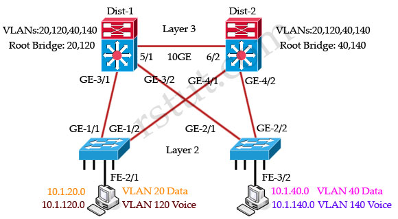
A. GE-1/2 and GE 2/1
B. GE-1/1 and GE-2/2
C. GE-3/2 and GE 4/1
D. no ports are in the blocking state
E. There is not enough information to determine which ports are in the blocking state.
Answer: D
Explanation
All these four switches are running MST and they are load-balancing. Dist-1 is the root bridge of VLANs 20 & 120 while Dist-2 is the root bridge of VLANs 40 & 140.
For VLANs 20, 120 switch Dist-1 is the root bridge so GE-4/1 & GE-4/2 links of Dist-2 are blocked:
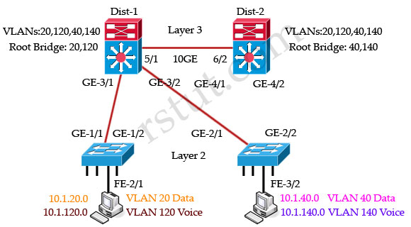
For VLANs 40, 140 switch Dist-2 is the root bridge so GE-3/1 & GE-3/2 links of Dist-1 are blocked:
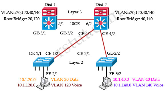
But notice that there are no ports in blocking state although some ports are blocked for specific VLANs. Remember that the blocking state in MST switch means that the port is blocked for all VLANs.
Question 9
Refer to the exhibit. In the diagram, the switches are running IEEE 802.1w RSTP. On which ports should root guard be enabled in order to facilitate deterministic root bridge election under normal and failure scenarios?

A. GE-3/1, GE-3/2
B. FE-2/1, FE-3/2
C. GE-1/1, GE-1/2
D. GE-4/1, GE-4/2
E. GE-2/1, GE-2/2
F. GE-3/1, GE-3/2, GE-4/1, GE-4/2, FE-2/1, FE-3/2
Answer: F
Explanation
Root Guard is a Cisco-specific feature that prevents a Layer 2 switched port from becoming a root port. It is enabled on ports other than the root port and on switches other than the root. If a Root Guard port receives a BPDU that might cause it to become a root port, then the port is put into “root-inconsistent” state and does not pass traffic through it. If the port stops receiving these BPDUs, it automatically re-enables itself.
This feature is sometimes recommended on aggregation layer ports that are facing the access layer, to ensure that a configuration error on an access layer switch cannot cause it to change the location of the spanning tree root switch (bridge) for a given VLAN or instance. Below is a recommended port’s features should be enabled in a network.
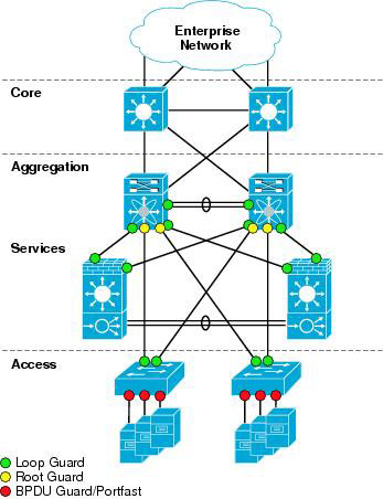
(Reference: http://www.cisco.com/en/US/docs/solutions/Enterprise/Data_Center/nx_7000_dc.html)
The port FE-2/1 & FE-3/2 should be turned on the Root Guard feature because hackers can try to plug these ports into other switches or try to run a switch-simulation software on these PCs. Imagine a new switch that is introduced into the network with a bridge priority lower than the current root bridge. In a normal STP operation, this new bridge can become the new Root Bridge and disrupt your carefully designed network. The recommended design is to enable Root Guard on all access ports so that a root bridge is not established through this port.
Note: The Root Guard affects the entire port. Therefore it applies to all VLANs on that port. To enable this feature, use the following command in interface configuration:
Switch(config-if)# spanning-tree guard root
Question 10
Loop guard and UniDirectional Link Detection both protect against Layer 2 STP loops. In which two ways does loop guard differ from UDLD in loop detection and prevention? (Choose two)
A. Loop guard can be used with root guard simultaneously on the same port on the same VLAN while UDLD cannot.
B. UDLD protects against STP failures caused by cabling problems that create one-way links.
C. Loop guard detects and protects against duplicate packets being received and transmitted on different ports.
D. UDLD protects against unidirectional cabling problems on copper and fiber media.
E. Loop guard protects against STP failures caused by problems that result in the loss of BPDUs from a designated switch port.
Answer: B E
Here you will find answers to Spanning Tree Protocol Questions – Part 2
Question 1
Which standard supports multiple instances of spanning tree?
A. 802.1 D
B. 802.1s
C. 802.1w
D. 802.1 z
Answer: B
Question 2
Spanning Tree Protocol calculates path cost based on which of these?
A. interface bandwidth
B. interface delay
C. interface bandwidth and delay
D. hop count
E. bridge priority
Answer: A
Question 3
In Layer 2 topologies, spanning-tree failures can cause loops in the network. These unblocked loops can cause network failures because of excessive traffic. Which two Catalyst 6500 features can be used to limit excessive traffic during spanning-tree loop conditions? (Choose two)
A. loop guard
B. storm control
C. storm suppression
D. broadcast suppression
E. BPDU guard
Answer: B D
Question 4
Why does RSTP have a better convergence time than 802.1 D?
A. it is newer
B. it has smaller timers
C. it has less overhead
D. it is not timer-based
Answer: D
Question 5
Under which two circumstances would an RSTP bridge flush its CAM table? (Choose two)
A. upon a port state change
B. upon receiving a topology change notification
C. when transitioning from discarding to forwarding
D. when transitioning from forwarding to discarding
E. only when changing from listening to discarding
F. when CAM resources have been completely used up
Answer: B C
Question 6
Which of these correctly identifies a difference between the way BPDUs are handled by 802.1w and 802.1 D?
A. 802.1D bridges do not relay BPDUs.
B. 802.1w bridges do not relay BPDUs.
C. 802.1D bridges only relay BPDUs received from the root.
D. 802.1w bridges only relay BPDUs received from the root.
Answer: C
Question 7
You have done a partial migration from 802.1 D STP to 802.1w STP. Which of the following is true?
A. 802.1 D and 802.1w intemperate only when the 802.1 D STP domain supports rapid convergence.
B. Ports leading to 802.1 D devices will run in compatibility mode, while the rest of the ports will run in 802.1 w mode.
C. This is an invalid configuration and a partial migration cannot be done.
D. The bridge timers will be set to match the 802.1 D devices.
E. A secondary root bridge will always be populated within the 802.1 D domain.
F. If the root bridge is selected within the 802.1 D domain, the whole STP domain will run in
Answer: B
Question 8
In the following network topology, there are three switches. All of them are configured to run STP. The network administrator has configured all switches in order for Link A to be the active link and Link B to be the standby link. When SB begins forwarding on Link B, a routing loop is formed. Why?
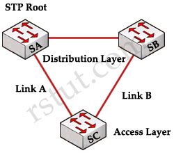
A. MISTP is enabled without RSTP.
B. There is a port duplex mismatch.
C. A single instance of STP is enabled instead of PVST.
D. PortFast is not enabled.
Answer: B
Explanation
When the network converges, link B will be blocked at one end. In this case, we suppose the port on SB is being blocked then it is still in blocking state until it stops receiving BPDU from a bridge that has a higher priority (in this case SA or SC). A port duplex mismatch can cause this state when the two endpoints of the connection between switch-switch are using different duplex settings. For example, one endpoint is operating at full-duplex while the other is using half-duplex. For example, the SA’s port connected to SB is set as “half-duplex” while SB’s port connected to SA is set as “full-duplex” as shown below.
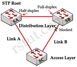
Because switch SB has configuration for full-duplex, it does not perform carrier sense before link access. Switch SB starts to send frames even if switch SA is already using the link. Switch A, operating at half-duplex mode, detects a collision and runs the backoff algorithm before the bridge attempts another transmission of the frame. If there is enough traffic from SB to SA, every packet that A sends, which includes the BPDUs, undergoes deferment or collision and eventually gets dropped. SB does not receive BPDUs from SA any more, SB think it has lost the root bridge. This leads SB to unblock the port connected to SC, which creates the loop.
Some of the situations in which the loss of BPDUs cause a blocked port to go into forwarding mode are:
+ Duplex Mismatch
+ Unidirectional Link
+ Packet Corruption
+ Resource Errors
+ PortFast Configuration Error
+ Awkward STP Parameter Tuning and Diameter Issues
+ Software Errors
(Reference: http://www.cisco.com/en/US/tech/tk389/tk621/technologies_tech_note09186a00800951ac.shtml)
Here you will find answers to VLAN & VTP Questions
Question 1
Which of these best describes the actions taken when a VTP message is received on a switch configured with the VTP mode “transparent”?
A. VTP updates are ignored and forwarded out all ports.
B. VTP updates are ignored and forwarded out trunks only.
C. VTP updates are made to the VLAN database and are forwarded out trunks only.
D. VTP updates are ignored and are not forwarded.
Answer: B
Question 2
Refer to the exhibit. Catalyst R is the root bridge for both VLAN 1 and VLAN 2. What is the easiest way to load-share traffic across both trunks and maintain redundancy in case a link fails, without using any type of EtherChannel link-bundling?

A. Increase the root bridge priority (increasing the numerical priority number) for VLAN 2 on Catalyst D so that port D2 becomes the root port on Catalyst D for VLAN 2.
B. Decrease the port priority on R2 for VLAN 2 on Catalyst R so that port D1 will be blocked for VLAN 2 and port D2 will remain blocked for VLAN 1.
C. Decrease the path cost on R2 on Catalyst R for VLAN 2 so that port D1 will be blocked for VLAN 2 and port D2 will remain blocked for VLAN 1.
D. Increase the root bridge priority (decreasing the numerical priority number) for VLAN 2 on Catalyst R so that R2 becomes the root port on Catalyst D for VLAN 2.
Answer: B
Explanation
First we should understand what will happen if nothing is configured (use default values). Because R is the root bridge so all of its ports will forward. D will need to block one of its ports to avoid a bridging loop between the two switches. But how does D select its blocked port? Well, the answer is based on the BPDUs it receives from R. A BPDU is superior than another if it has:
1. A lower Root Bridge ID
2. A lower path cost to the Root
3. A lower Sending Bridge ID
4. A lower Sending Port ID
These four parameters are examined in order. In this case, all the BPDUs sent by R have the same Root Bridge ID, same path cost to the Root and same Sending Bridge ID. The only parameter left to select the best one is the Sending Port ID (Port ID = port priority + port index). If using default values, the default port priority’s value is 32 or 128 (128 is much more popular today), so D will compare port index values, which are unique to each port on the switch, and because port R2 is inferior to port R1 (the port’s number of R2 is higher than that of R1, for example port Fa0/2 is inferior to port Fa0/1), D will select the port connected with port R1 as its root port and block the other port.
The problem here is port D2 is blocked for both VLAN 1 & 2 and that means we can’t use the underneath link for load-sharing. The underneath link is just used in the case the above link fails.
Now as you can guess, the easiest way to load-share traffic across both trunks is decreasing the port priority on R2 for VLAN 2 on Catalyst R so that port D1 will be blocked for VLAN 2. Notice that “decreasing” here means make that port ID superior to the other port.
Question 3
The network administrator is trying to add Switch1 to the network, but the 802.1 Q trunk is not coming up. Switch1 was previously tested in the laboratory and its trunk configuration worked fine. What are three possible causes of this problem? (Choose three)
A. The trunking configuration mode on Switch1 is set to Off.
B. The trunking configuration mode on the other end is set to On.
C. The trunking configuration mode on the other end is set to Desirable.
D. Cisco Discovery Protocol is not running on the other end.
E. There is a VTP domain name mismatch.
F. Switch1 does not support 802.1Q.
Answer: B C E
Explanation
There are 5 possible trunking modes for a switch port:
+ Auto: this is the default mode. In this mode, a port will become a trunk port if the device the port is connected to is set to the on or desirable mode.
+ Desirable: allows the port to become a trunk port if the device the port is connected to is set to the on, desirable, or auto mode
+ On: sets the port to permanent trunking mode.
+ Nonegotiate: sets the port to permanent trunking mode without sending Dynamic Trunking Protocol (DTP) frames
+ Off: sets the port to permanent non-trunking mode
In this case, we can guess the trunking mode of Switch 1 is “auto” (default mode). When in the laboratory, the trunking mode of the other end is set to “On” or “Desirable” so 2 switches can negotiate and the link becomes trunk with no problem. But when plugging to the network, other switches may have the trunking mode set to “auto” so the 802.1Q trunk is not coming up -> B C are correct.
Of course these switches need to be in the same VTP domain so that they can “talk” with each other -> E is correct.
Question 4
Refer to the exhibit. The Layer 2 network uses VTP to manage its VLAN database. A network designer created all VLANs on the VTP server (switch 1) and it has been advertised through VTP to all other VTP clients (switches 2 through 4). Due to network growth, a network operator decided to add a new switch between switch 1 and switch 3. The network operator has been instructed to use a refurbished switch and use a VTP client. Which three of these factors should the network operator consider to minimize the impact of adding a new switch? (Choose three)


A. Pay special attention to the VTP revision number, because the higher value takes the priority.
B. Configure all VLANs manually on the new switch in order to avoid connectivity issues.
C. A trunk should be established between the new switch and switches 1 and 3 as VTP only runs over trunk links.
D. Set at least the VTP domain name and password to get the new switch synchronized.
E. An ISL trunk should be established between the new switch and switches 1 and 3, because VTP only runs over ISL.
F. Pay special attention to the VTP revision number, because the lower value takes the priority.
Answer: A C D
Explanation
VTP should be used whenever we have more than 1 switch with multiple VLANs. It helps us save much time so configuring all VLANs manually is just a waste of time -> B is not correct.
VLAN Trunking Protocol (VTP) can operate over 802.1q or ISL on FastEthernet link.
+ On ISL: Switch(config-if)#switchport trunk encapsulation isl
+ On 802.1q: Switch(config-if)#switchport trunk encapsulation dot1q
-> E is not correct
Note: The 2940/2950 switches only support 802.1q encapsulation with the switchport mode trunk command. The switch will automatically use 802.1q encapsulation.
Each time a VTP updates are sent out, the revision number is increased by 1. Any time a switch sees a higher revision
number, it knows the information that it’s receiving is more current, and it will overwrite the current database with that new information.
Here you will find answers to OSPF Questions
Question 1
Which information is carried in an OSPFv3 intra-area-prefix LSA?
A. IPv6 prefixes
B. link-local addresses
C. solicited node multicast addresses
D. IPv6 prefixes and topology information
Answer: A
Explanation
The OSPFv3’s new LSA, the Intra-area Prefix LSA (type 9), handles intra-area network information that was previously included in OSPFv2 type 2 LSAs. It is used in order to advertise one or more IPv6 prefixes. The prefixes are associated with router segment, stub network segment or transit network segment.
Intra-area prefix LSAs (type 9) & Inter-Area-Prefix-LSA (type 3) carry all IPv6 prefix information, which, in IPv4, is included in router LSAs and network LSAs.
Note: An address prefix is represented by three fields: prefix length, prefix options, and address prefix. In OSPFv3, addresses for these LSAs are expressed as prefix, prefix length instead of address, mask.
Question 2
Which one of these statements is true of OSPF type 5 LSAs?
A. They are used to summarize area routes to other areas.
B. They are used in not-so-stubby areas to propagate external routes.
C. They are used to notify areas of the ASBR.
D. They are flooded to all areas (external route).
Answer: D
Explanation
Type 5 external link LSAs are used to advertise external routes originated from an ASBR. They are flooded through the whole OSPF domain.
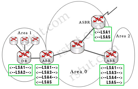
(Note: The dashed arrows show the directions of LSAs in this example)
Below is a summary of OSPF Link-state advertisements (LSAs)
Router link LSA (Type 1) – Each router generates a Type 1 LSA that lists its neighbors and the cost to each. LSA Type 1 is only flooded inside the router’s area, does not cross ABR.
Network link LSA (Type 2) – is sent out by the designated router (DR) and lists all the routers on the segment it is adjacent to. Types 2 are flooded within its area only; does not cross ABR. Type 1 & type 2 are the basis of SPF path selection.
Summary link LSA (Type 3) – ABRs generate this LSA to send between areas (so type 3 is called inter-area link). It lists the networks inside other areas but still belonging to the autonomous system and aggregates routes. Summary links are injected by the ABR from the backbone into other areas and from other areas into the backbone.
Summary LSA (Type 4) – Generated by the ABR to describe routes to ASBRs. In the above example, the only ASBR belongs to area 0 so the two ABRs send LSA Type 4 to area 1 & area 2 (not vice versa). This is an indication of the existence of the ASBR in area 0. Note: Type 4 LSAs contain the router ID of the ASBR.
External Link LSA (LSA 5) – Generated by ASBR to describe routes redistributed into the area (which means networks from other autonomous systems). These routes appear as E1 or E2 in the routing table. E2 (default) uses a static cost throughout the OSPF domain as it only takes the cost into account that is reported at redistribution. E1 uses a cumulative cost of the cost reported into the OSPF domain at redistribution plus the local cost to the ASBR. Type 5 LSAs flood throughout the entire autonomous system but notice that Stubby Area and Totally Stubby Area do not accept Type 5.
Multicast LSA (Type 6) are specialized LSAs that are used in multicast OSPF applications.
NSSA External LSA (Type 7) – Generated by an ASBR inside a NSSA to describe routes redistributed into the NSSA. LSA 7 is translated into LSA 5 as it leaves the NSSA. These routes appear as N1 or N2 in the ip routing table inside the NSSA. Much like LSA 5, N2 is a static cost while N1 is a cumulative cost that includes the cost upto the ASBR
(Reference: http://www.cisco.com/en/US/tech/tk365/technologies_white_paper09186a0080094e9e.shtml#appa1)
Question 3
Which OSPF LSA type does an ASBR use to originate a default route into an area?
A. LSA 1
B. LSA 3
C. LSA 4
D. LSA 5
E. LSA 7
Answer: D
Explanation
By default, the OSPF router does not generate a default route into the OSPF domain. In order for OSPF to generate a default route, you must use the default-information originate command. With this command, the router will advertise type 5 LSA with a link ID of 0.0.0.0.
(Reference: http://www.cisco.com/en/US/tech/tk365/technologies_configuration_example09186a00801ec9f0.shtml)
Question 4
Refer to the exhibit. Routers A and B are directly connected and running OSPF, but they are unable to form a neighbor relationship. What is the most likely cause?
|
Router A relevant configuration: router ospf 1 Router B relevant configuration: router ospf 10 |
A. The routers are not on the same network.
B. The network statements do not match.
C. The process number does not match.
D. The MTU does not match.
E. The OSPF cost does not match.
F. There is a physical issue with the cable.
Answer: D
Explanation
OSPF sends the interface MTU in a database description packet. If there is a MTU mis-match, OSPF will not form an adjacency and they are stuck in exstart/exchange state. The interface MTU option was added in RFC 2178. Previously, there was no mechanism to detect the interface MTU mismatch. This option was added in Cisco IOS Software Release 12.0.3 and later.
If the router with the higher MTU sends a packet larger that the MTU set on the neighboring router, the neighboring router ignores the packet and the neighbor state remains in exstart.
Note: By default, the MTU for Ethernet is 1500 bytes. We can check the OSPF adjacency process with the command “show ip ospf neighbor”.
(Reference: http://www.cisco.com/en/US/tech/tk365/technologies_tech_note09186a0080093f0d.shtml)
Question 5
Which two of these steps are minimum requirements to configure OSPFv3 under IPv6? (Choose two)
A. Configure a routing process using the command ipv6 router ospf [process-id].
B. Add the network statement for the interfaces on which OSPF will run.
C. Configure OSPF on the interface that it will run on.
D. Use the passive-interface command on the interfaces on which OSPF should not run.
E. Enable routing.
Answer: C E
Explanation
The first step to configure OSPFv3 under IPv6 is to enable IPv6 unicast routing:
R1(config)# ipv6 unicast-routing
Also we need to enable the OSPF process:
R1(config)# ipv6 router ospf 1
There are a few changes in configuring OSPFv3 vs OSPF for IPv4. Instead of using the “network” and “area” commands in ospf router configuration mode you now configure OSPFv3 on a per interface basis using the ipv6 ospf
R1(config)# interface fa0/0
R1(config-if)# ipv6 ospf 1 area 0
Note: The “network” command does not exist in OSPFv3.
Question 6
Refer to the exhibit. How would you get the 1.1.1.1 network into the OSPF database?
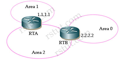
A. Configure RTA as an ASBR.
B. Redistribute connected routes on RTA into OSPF.
C. Set up a virtual link between area 1 and area 0.
D. Set up a virtual link between area 1 and area 2.
E. Add a static route into RTB and enter it into OSPF.
F. Place a network 1.1.1.0 0.0.0.0 command into RTB.
G. Set up a unique router ID on RTA using an RFC 1918 address.
H. Change area 0 on RTB to area 1
Answer: C
Explanation
Recall that in OSPF, area 0 is called backbone area and all other areas connect directly to it. In the exhibit above, area 1 is not directly connected with area 0 so we need to set up a virtual link between area 1 & area 0 so that the networks in area 1 can be recognized in area 0. The virtual-link configuration is shown below:
RTB(config)#router ospf 1
RTB(config-router)#area 2 virtual-link 1.1.1.1
RTA(config)#router ospf 1
RTA(config-router)#area 2 virtual-link 2.2.2.2
Notice that the router-id in the “area … virtual-link
Question 7
The core of a network has four routers connected in a square design with Gigabit Ethernet links using /30 subnets. The network is used to carry voice traffic and other applications. Convergence time is taking more than expected. Which three actions would you take to improve OSPF convergence time? (Choose three)
A. Increase MTU of the interfaces to accommodate larger OSPF packets.
B. Change the network type to point-to-point on those links.
C. Reduce SPF initial timer.
D. Increase hello interval to avoid adjacency flapping.
E. Enable OSPF.
Answer: B C E
Here you will find answers to EIGRP Questions
Question 1
Refer to the exhibit. In this network, R1 is configured not to perform autosummarization within EIGRP. What routes will R3 learn from R2 through EIGRP?
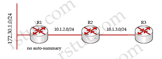
A. 172.30.1.0/24 and 10.1.2.0/24; EIGRP only performs autosummarization at the edge between two major networks.
B. 172.30.0.0/16 and 10.1.2.0/24; R2 will perform autosummarization, although R1 will not.
C. Since R2 is configured without autosummarization, it will not propagate the 172.30.1.0/24 route.
D. 172.30.0.0/8 and 10.0.0.0/8.
Answer: A
Explanation
EIGRP performs an auto-summarization each time it crosses a border between two different major networks. For example, in the topology below R3 will auto-summary and advertise only 10.0.0.0/8 network to R4 router.
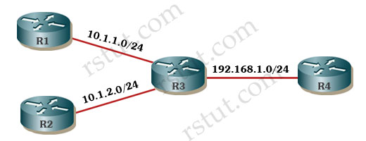
In the above question, if R1 is configured with “auto-summary”, it will advertise the summarized 172.30.0.0/16 network to R2.
Question 2
Though many options are supported in EIGRPv6, select two options from the below list that are supported. (Choose two)
A. VRF
B. auto-summary
C. per-interface configuration
D. prefix-list support via route-map
E. prefix-list support via distribute-list
Answer: C E
Explanation
Below is some information EIGRPv6:
IPv6 EIGRP and IPV4 EIGRP are very similar in concept except for the following differences:
* IPv6 is configured on interface basis (like OSPFv3 and RIPng) and networks are advertised based on interface command -> C is correct.
* When configured on interface, IPv6 EIGRP is initially placed in “shutdown” state
* As with OSPFv3, IPv6 EIGRP require a router-id in IPv4 format
* Passive interfaces can only be configured in the routing process mode
* Need for extra memory resources and supported in IOS 12.4(6)T and later
* No split horizon in IPv6 because it is possible to get multiple prefixes per interface
* No concept of classful routing in IPv6 EIGRP consequently no automatic summary -> B is not correct
EIGRPv6 uses the router configuration command “distribute-list prefix-list” to perform route filtering, and when configuring route filtering the “route-map” command is not supported -> E is correct but D is not.
Virtual Routing and Forwarding (VRF) is also supported in EIGRPv6.
Question 3
Refer to the exhibit. Routers A and B are directly connected. Given the configuration, how many EIGRP routes will router B see in its routing table?
|
Router A relevant configuration router eigrp 100 Router B relevant configuration router eigrp 100 |
A.0
B. 1
C.2
D. 3
E. 4
Answer: A
Explanation
In this question, router A does not advertise its “network 10.10.1.0 0.0.0.255” in the EIGRP process (the network connected with router B) so no EIGRP neighbor relationship is established between two routers. If we use the “show ip route” command on both routers, we just see a directly connected network 10.10.1.0/24 like this:
| Gateway of last resort is not set 10.0.0.0/24 is subnetted, 1 subnets C 10.10.1.0 is directly connected, FastEthernet0/0 |
For your information, even if we use the “network 10.10.1.0 0.0.0.255” in the EIGRP process of router A we still don’t see any EIGRP route because router A does not have any interfaces belonging to networks 10.1.1.0/24, 10.2.1.0/24, 172.16.2.0/24 -> it will not advertise these networks to router B.
Question 4
Refer to the exhibit. Routers A and B are directly connected and running EIGRP, but they are unable to form a neighbor relationship. What is the most likely cause?
|
Router A relevant configuration: router eigrp 100 Router B relevant configuration: router eigrp 100 |
A. The network statements are misconfigured.
B. The IP address statements are misconfigured.
C. The autonomous system is missconfigured.
D. There is a physical issue with the cable.
Answer: B
Explanation
To form neighbor relationship in EIGRP, these conditions must be met:
* Pass the authentication process
* Have the same configured AS number
* Must believe that the source IP address of a received Hello is in that router’s primary connected subnet on that interface
* Match K values
The third item means that the primary ip address of the neighbor must be in the same subnet with the primary ip address of the received interface. But in this case the primary ip address of router A is 10.10.10.1/30 and it is not in the same subnet with the primary ip address of router B 10.10.10.6/30 -> no EIGRP neighbor relationship is formed.
Question 5
You add the following commands into a routed topology:
router eigrp 1
variance 3
traffic-share min across-interfaces
Users now complain about voice quality in your VoIP system. What should be done?
A. Add the command: router eigrp 1 traffic-share voice interface fast 0/0.
B. Reconfigure EIGRP to recognize voice packets.
C. Remove the variance from the configuration.
D. Reconfigure the VoIP system to use RTP sequence number headers.
E. Use an H.323 gatekeeper for your VoIP system to negotiate an H.245 uneven packet buffer.
F. Reconfigure EIGRP to version 2.
Answer: D or E
Explanation
This is a tough question to answer. I have no idea about the command “traffic-share min across-interfaces” and do a search and the best explanation I found is: traffic-share min command causes EIGRP to divide traffic only among the routes with the best metric. When the traffic-share min command is used with the across-interfaces keyword, an attempt is made to use as many different interfaces as possible to forward traffic to the same destination.
Therefore with the configuration above, EIGRP will only use equal-cost load-balancing feature even when the variance command is used. However, if you use both the traffic-share min command and variance command, even though traffic is sent over the minimum-cost path only, all feasible routes get installed into the routing table, which decreases the convergence times. But the voice quality is still the same so C is not a correct answer.
A is not correct as there is no “traffic-share voice ….” command.
B is not correct as EIGRP can not recognize voice packets.
F is not correct because EIGRP does not have version 2.
Note: EIGRP routing process will install all paths with metric < best_metric * variance into the local routing table. Here metric is the full metric of the alternate path (FD) and best_metric is the metric of the primary path
Question 6
Based on the network displayed in the exhibit, both R1 and R2 are configured as EIGRP stub routers. If the link between R1 and R3 is down, will R3 still be able to reach 192.168.1.0/24, and why or why not?
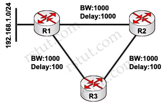
A. No. R3 would remove its route to 192.168.1.0/24 through R1, but would not query R2 for an alternate route, since R2 is a stub.
B. No. The path through R2 would always be considered a loop at R3.
C. Yes. When a directly connected link fails, a router is allowed to query all neighbors, including stub neighbors, for an alternate route.
D. Yes, because R3 would know about both routes, through R1 and R2, before the link between R1 and R3 failed.
Answer: A
Question 7
Study the following network topology carefully. The routers R1, R2 and R3 are connected to each other. EIGRP is running in this network. When the link between R1 and R3 is down, what will R4 receive from R3?
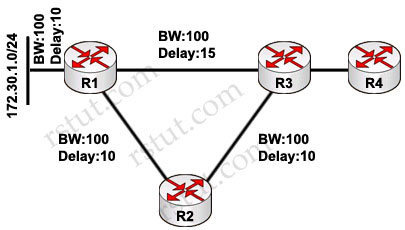
A. R4 will not receive any updates or queries, because R3 will simply move to the path through R2
B. R4 will receive an update noting R3’s higher cost to reach 172.30.1.0/24
C. R4 will receive a query, because R3 will mark 172.30.1.0/24 as active when the link between R1 and R4 failed
D. R4 will not receive any packets, since R3 is not using the link to R1 to reach 172.30.1.0/24
Answer: B
Here you will find answers to BGP Questions
Question 1
Two routers configured to run BGP have been connected to a firewall, one on the inside interface and one on the outside interface. BGP has been configured so the two routers should peer, including the correct BGP session endpoint addresses and the correct BGP session hop-count limit (EBGP multihop). What is a good first test to see if BGP will work across the firewall?
A. Attempt to TELNET from the router connected to the inside of the firewall to the router connected to the outside of the firewall. If telnet works, BGP will work, since telnet and BGP both use TCP to transport data.
B. Ping from the router connected to the inside interface of the firewall to the router connected to the outside interface of the firewall. If you can ping between them, BGP should work, since BGP uses IP to transport packets.
C. There is no way to make BGP work across a firewall without special configuration, so there is no simple test that will show you if BGP will work or not, other than trying to start the peering session.
D. There is no way to make BGP work across a firewall.
Answer: A
Question 2
Which types of prefixes will a router running BGP most likely advertise to an IBGP peer, assuming it is not configured as a route reflector?
A. prefixes received from any other BGP peer and prefixes locally originated via network statements or redistributed
B. all prefixes in its routing table
C. prefixes received from EBGP peers and prefixes locally originated via network statements or redistributed
D. prefixes received from EBGP peers and prefixes received from route reflectors
E. prefixes received from other IBGP peers, prefixes received from EBGP peers, and prefixes redistributed to BGP
F. prefixes received from other IBGP peers and prefixes received from route reflectors
Answer: C
Question 3
You have two EBGP peers connected via two parallel serial lines. What should you do to be able to load-balance between two EBGP speakers over the parallel serial lines in both directions?
A. nothing, BGP automatically load-balances the traffic between different autonomous systems on all available links
B. peer between the eBGP speaker’s loopbacks, configuring eBGP multihop as required, and use an IGP to load-share between the two equal-cost paths between the loopback addresses
C. configure a loopback as update source for both EBGP peers and have on each AS an IGP to introduce two equal-cost paths to reach the EBGP peer loopback address; it is also necessary to use the next- hop-self command
D. use the ebgp-load-balance command on the neighbor statement on both sides
E. configure a loopback as update source for both EBGP peers and have on each AS an IGP to introduce two equal-cost paths to reach the peer loopback address; it is also necessary to use the ebgp-multihop and next-hop-self commands
Answer: B
Question 4
Which of these best identifies the types of prefixes a router running BGP will advertise to an EBGP peer?
A. prefixes received from any other BGP peer and prefixes locally originated via network statements or redistributed to BGP
B. all prefixes in its IP routing table
C. only prefixes received from EBGP peers and prefixes locally originated via network statements or redistributed
D. only prefixes received from EBGP peers and prefixes received from route reflectors
E. all prefixes in its routing table except the prefixes received from other EBGP peers
E. all prefixes in its routing table except the prefixes received from other IBGP peers
Answer: A
Question 5
Refer to the exhibit. Users on the 199.155.24.0 network are unable to reach the 172.16.10.0 network. What is the most likely solution?
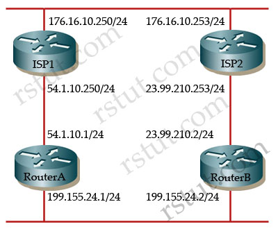 |
Router A relevant configuration Router B relevant configuration Router ISP1 relevant configuration Router ISP2 relevant configuration |
A. Router ISP1 should be configured to peer with router B.
B. Router ISP2 should be configured with no synchronization.
C. Router ISP1 should be configured with no synchronization.
D. Router ISP2 should be configured with no auto-summary.
E. Router ISP1 or IPS2 should be configured with network 176.16.10.0 mask 255.255.255.0.
Answer: E
Question 6
Two BGP peers connected through a routed firewall are unable to establish a peering relationship. What could be the most likely cause?
A. BGP peers must be Layer 2-adjacent.
B. EBGP multihop is not configured.
C. The firewall is not configured to allow IP protocol 89.
D. The firewall is not configured to allow UDP 179.
Answer: B
Question 7
Refer to the exhibit. BGP-4 routing to the Internet, in normal behavior, may create asymmetrical routing for different prefixes. The BGP routing table indicates that traffic should follow the paths indicated in the exhibit, but packets are not going further than the border router in AS 4. What could be the cause of this problem?
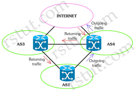
A. TCP Intercept is configured in AS 4.
B. Unicast Reverse Path Forwarding is configured in loose mode in this router.
C. Packets may be leaving AS 1 without the BGP routing flag set to 1.
D. Unicast Reverse Path Forwarding is configured in strict mode in this router.
E. There is a missing Unicast Reverse Path Forwarding configuration.
Answer: D
Explanation
Both UniDirectional Link Detection (UDLD) and Loop Guard protect a switch trunk port from causing loops. Both features prevent switch ports from errantly moving from a blocking to a forwarding state when a unidirectional link exists in the network.
Unidirectional links are simply links for which one of the two transmission paths on the link has failed, but not both. This can happen as a result of miscabling, cutting one fiber cable, unplugging one fiber, GBIC problems, or other reasons
UDLD – Uses Layer 2 messaging to decide when a switch can no longer receive frames from a neighbor. The switch whose transmit interface did not fail is placed into an err-disabled state.
Loop Guard – When normal BPDUs are no longer received, the port does not go through normal STP convergence, but rather falls into an STP loop-inconsistent state.
(Reference: CCIE Routing and Switching Exam Certification Guide)
Here you will find answers to Miscellaneous Questions
Question 1
You replaced your Layer 3 switch, which is the default gateway of the end users. Many users cannot access anything now, including email, Internet, and other applications, although other users do not have any issues. All of the applications are hosted in an outsourced data center. In order to fix the problem, which one of these actions should you take?
A. Clear the MAC address table in the switch.
B. Clear the ARP cache in the switch:
C. Clear the ARP cache in the end devices.
D. Clear the ARP cache in the application servers.
Answer: C
Question 2
Refer to the exhibit. Look at the command output. What would be the most probable reason for this port-ID mismatch?
|
Switch 1#show cdp neighbors
Switch1# Switch 2#show cdp neighbors
Switch2# |
A. spanning-tree misconfiguration
B. speed mismatch configuration
C. cabling problem
D. configuration problem
Answer: C
Question 3
When troubleshooting a network, the output of the command show interfaces indicates a large number of runts. What is a runt?
A. the number of packets that are discarded because they exceed the maximum packet size of the medium
B. errors created when the CRC generated by the originating LAN station or far-end device does not match the checksum calculated from the data received.
C. the number of packets that are discarded because they are smaller than the minimum packet size of the medium
D. the number of received packets that were ignored by the interface because the interface hardware ran low on internal buffers
E. the number of times that the interface requested another interface within the router to slow down
Answer: C
Explanation
A runt is a packet that fails to meet the minimum size standard (below 64 bytes for Ethernet packet). Network protocols such as Ethernet often require that packets be a minimum number of bytes in order to travel the network. Runts are often the result of packet collisions along a busy network or can result from faulty hardware that is forming the packets or from corrupted data being sent across the network.
Question 4
A network administrator has applied the NTP peer statement to a Cisco IOS router. Which additional function is simultaneously being used on this router?
A. static server
B. symmetric active mode
C. NTP broadcast client
D. static client
Answer: B
Question 5
NTP will allow you to establish which three relationships between two networking devices?
A. client
B. server
C. broadcast
D. anycast
Answer: A B C
Question 6
Which command can be used to solve the problem caused by a router configured with multiple DHCP pools?
A. host
B. default-gateway
C. network
D. ip helper
Answer: A