OSPF Questions
Question 1
According to RFC 4577, OSPF for BGP/MPLS IP VPNs, when must the down bit be set?
A when an OSPF route is distributed from the PE to the CE, for Type 3 LSAs
B. when an OSPF route is distributed from the PE to the CE, for Type 5 LSAs
C. when an OSPF route is distributed from the PE to the CE, for Type 3 and Type 5 LSAs
D. when an OSPF route is distributed from the PE to the CE, for all types of LSAs
Answer: C
Explanation
If an OSPF route is advertised from a PE router into an OSPF area, the Down bit (DN) is set. Another PE router in the same area does not redistribute this route into iBGP of the MPLS VPN network if down is set.
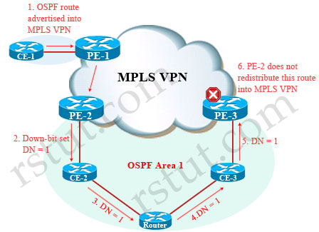
The RFC 4577 says:
“When a type 3 LSA is sent from a PE router to a CE router, the DN bit in the LSA Options field MUST be set. This is used to ensure that if any CE router sends this type 3 LSA to a PE router, the PE router will not redistribute it further. When a PE router needs to distribute to a CE router a route that comes from a site outside the latter’s OSPF domain, the PE router presents itself as an ASBR (Autonomous System Border Router), and distributes the route in a type 5 LSA. The DN bit [OSPF-DN] MUST be set in these LSAs to ensure that they will be ignored by any other PE routers that receive them.”
For more information about Down bit according to RFC 4577 please read more here: http://tools.ietf.org/html/rfc4577#section-4.2.5.1.
Question 2
Refer to the exhibit.
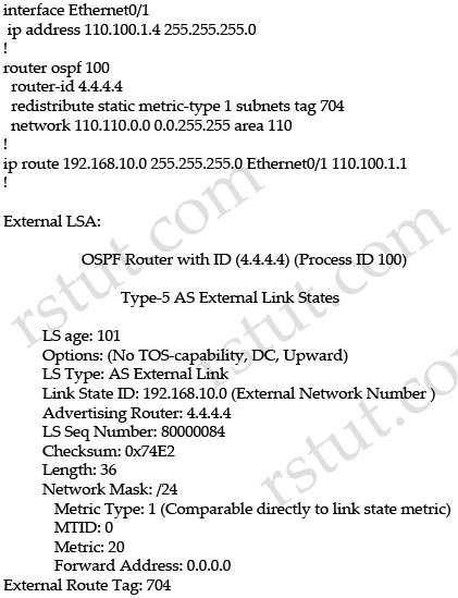
Which option explains why the forwarding address is set to 0.0.0.0 instead of 110.100.1.1?
A. The interface Ethernet0/1 is in down state.
B. The next-hop ip address 110.100.1.1 is not directly attached to the redistributing router.
C. The next-hop interface (Ethernet0/1) is specified as part of the static route command; therefore, the forwarding address is always set to 0.0.0.0.
D. OSPF is not enabled on the interface Ethernet0/1.
Answer: D
Explanation
From the output of the “show ip ospf database” command (although this command is not shown) we can conclude this is an ASBR (with Advertising Router is itself) and E0/1 is the ASBR’s next hop interface for other routers to reach network 192.168.10.0.
The Forwarding Address is determined by these conditions:
* The forwarding address is set to 0.0.0.0 if the ASBR redistributes routes and OSPF is not enabled on the next hop interface for those routes.
* These conditions set the forwarding address field to a non-zero address:
+ OSPF is enabled on the ASBR’s next hop interface AND
+ ASBR’s next hop interface is non-passive under OSPF AND
+ ASBR’s next hop interface is not point-to-point AND
+ ASBR’s next hop interface is not point-to-multipoint AND
+ ASBR’s next hop interface address falls under the network range specified in the router ospf command.
* Any other conditions besides these set the forwarding address to 0.0.0.0.
-> We can see E0/1 interface is not running OSPF because it does not belong to network 110.110.0.0 0.0.255.255 which is declared under OSPF process -> F.A address is set to 0.0.0.0.
(Reference: http://www.cisco.com/c/en/us/support/docs/ip/open-shortest-path-first-ospf/13682-10.html)
Question 3
Refer to the exhibit.
| router ospf 100 router-id 4.4.4.4 area 110 nssa summary-address 192.168.0.0 255.255.0.0 nssa-only redistribute static metric-type 1 subnets tag 704 network 110.110.0.0 0.0.255.255 area 110 |
This is the configuration of the ASBR of area 110. Which option explains why the remote ABR should not translate the type 7 LSA for the prefix 192.168.0.0/16 into a type 5 LSA?
A. The remote ABR translates all type 7 LSA into type 5 LSA, regardless of any option configured in the ASBR.
B. The ASBR sets the forwarding address to 0.0.0.0 which instructs the ABR not to translate the LSA into a type 5 LSA.
C. The ASBR originates a type 7 LSA with age equal to MAXAGE 3600.
D. The ABR clears the P bit in the header of the type 7 LSA for 192.168.0.0/16.
Answer: D
Explanation
When external routing information is imported into an NSSA, LSA Type 7 is generated by the ASBR and it is flooded within that area only. To further distribute the external information, type 7 LSA is translated into type 5 LSA at the NSSA border. The P-bit in LSA Type 7 field indicates whether the type 7 LSA should be translated. This P-bit is automatically set by the NSSA ABR (also the Forwarding Address (FA) is copied from Type 7 LSA). The P-bit is not set only when the NSSA ASBR and NSSA ABR are the same router for the area . If bit P = 0, then the NSSA ABR must not translate this LSA into Type 5.

The nssa-only keyword instructs the device to instigate Type-7 LSA with cleared P-bit, thereby, preventing LSA translation to Type 5 on NSSA ABR device.
Note: If a router is attached to another AS and is also an NSSA ABR, it may originate a both a type-5 and a type-7 LSA for the same network. The type-5 LSA will be flooded to the backbone and the type-7 will be flooded into the NSSA. If this is the case, the P-bit must be reset (P=0) in the type-7 LSA so the type-7 LSA isn’t again translated into a type-5 LSA by another NSSA ABR.
Question 4
Which statement about OSPF multiaccess segments is true?
A. The designated router is elected first.
B. The designated and backup designated routers are elected at the same time.
C. The router that sent the first hello message is elected first.
D. The backup designated router is elected first.
Answer: D
Explanation
According to the RFC, the BDR is actually elected first, followed by the DR. The RFC explains why:
“The reason behind the election algorithm’s complexity is the desire for an orderly transition from Backup Designated Router to Designated Router, when the current Designated Router fails. This orderly transition is ensured through the introduction of hysteresis: no new Backup Designated Router can be chosen until the old Backup accepts its new Designated Router responsibilities.
The above procedure may elect the same router to be both Designated Router and Backup Designated Router, although that router will never be the calculating router (Router X) itself.”
(Reference: http://www.ietf.org/rfc/rfc2328.txt – [Page 76])
Question 5
Consider a network that mixes link bandwidths from 128 kb/s to 40 Gb/s. Which value should be set for the OSPF reference bandwidth?
A. Set a value of 128.
B. Set a value of 40000.
C. Set a manual OSPF cost on each interface
D. Use the default value.
E. Set a value of 40000000.
F. Set a value of 65535.
Answer: C
Question 6
Which statement about a type 4 LSA in OSPF is true?
A. It is an LSA that is originated by an ABR, that is flooded throughout the AS, and that describes a route to the ASBR.
B. It is an LSA that is originated by an ASBR, that is flooded throughout the AS, and that describes a route to the ASBR.
C. It is an LSA that is originated by an ASBR, that is flooded throughout the area, and that describes a route to the ASBR.
D. It is an LSA that is originated by an ABR, that is flooded throughout the AS, and that describes a route to the ABR.
E. It is an LSA that is originated by an ABR, that is flooded throughout the area, and that describes a route to the ASBR.
Answer: E
Explanation
LSA Type 4 (called Summary ASBR LSA) is generated by the ABR to describe an ASBR to routers in other areas so that routers in other areas know how to get to external routes through that ASBR.

Question 7
Which two functions are performed by the DR in OSPF? (Choose two)
A. The DR originates the network LSA on behalf of the network.
B. The DR is responsible for the flooding throughout one OSPF area.
C. The DR forms adjacencies with all other OSPF routers on the network, in order to synchronize the LSDB across the adjacencies.
D. The DR is responsible for originating the type 4 LSAs into one area.
Answer: A C
Explanation
DR originates the network LSA (LSA Type 2) which lists all the routers on the segment it is adjacent to -> A is correct.
Types 2 are flooded within its area only; does not cross ABR -> B is incorrect.
The broadcast and non-broadcast network types elect a DR/BDR. They form adjacencies to all other OSPF routers on the network and help synchronize the Link State Database (LSDB) across the adjacencies -> C is correct.
LSAs Type 4 are originated by the ABR to describe an ASBR to routers in other areas so that routers in other areas know how to get to external routes through that ASBR -> D is incorrect.
Note: To learn more about OSPF LSA Types, please read our OSPF LSA Types Tutorial.
Question 8
Refer to the exhibit.

Which two statements are true? (Choose two)
A. This is the output of the show ip ospf command.
B. This is the output of the show ip protocols command.
C. This router is an ABR.
D. This router is an ASBR.
E. Authentication is not configured for the area.
Answer: A E
Question 9
Refer to the exhibit.
| R1 ! interface Fastethernet0/0 ip address 10.1.1.5 255.255.255.0 ! router ospf 1 network 10.1.1.5 0.0.0.0 area 0 passive-interface default ! R2 ! interface FastEthernet0/1 ip address 10.1.1.6 255.255.255.0 ! router ospf 10 network 10.1.1.6 0.0.0.0 area 0 ! |
Which additional configuration is necessary for R1 and R2 to become OSPF neighbors?
A.
R1
!
router ospf 1
no passive-interface FastEthernet0/0
!
B.
R2
!
router ospf 10
no network 10.1.1.6 0.0.0.0 area 0
network 10.1.1.6 0.0.0.0 area 1
!
C.
R1
!
interface FastEthernet0/0
ip ospf mtu-ignore
!
R2
!
interface FastEthernet0/1
ip ospf mtu-ignore
!
D.
R1
!
no router ospf 1
router ospf 10
network 10.1.1.5 0.0.0.0 area 0
Answer: A
Question 10
Refer to the exhibit.
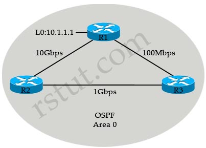
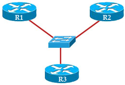
R3 prefers the path through R1 to reach host 10.1.1.1.
Which option describes the reason for this behavior?
A. The OSPF reference bandwidth is too small to account for the higher speed links through R2.
B. The default OSPF cost through R1 is less than the cost through R2.
C. The default OSPF cost through R1 is more than the cost through R2.
D. The link between R2 and R1 is congested.
Answer: A
Explanation
The default formula to calculate OSPF bandwidth is BW = Bandwidth Reference / interface bandwidth [bps] = 10^8 / / interface bandwidth [bps]
BW of the R1-R3 link = 10^8 / 100Mbps = 10^8 / 10^8 = 1
BW of the R2-R3 link = 10^8 / 1Gbps = 10^8 / 10^9 = 1 (round up)
Therefore OSPF considers the two above links have the same Bandwidth -> R3 will go to 10.1.1.1 via the R1-R3 link. The solution here is to increase the Bandwidth Reference to a higher value using the “auto-cost reference-bandwidth” command under OSPF router mode. For example:
Router(config)#router ospf 1
Router(config-router)#auto-cost reference-bandwidth 10000
This will increase the reference bandwidth to 10000 Mbps which increases the BW of the R2-R3 link to 10^10 / 10^8 = 100.
Question 11
Refer to the exhibit.

Why is the prefix 1.1.1.1/32 not present in the routing table of R1?
A. There is a duplicate router ID
B. There is a subnet mask mismatch on Ethernet0/0
C. The router LSA has an invalid checksum
D. There is an OSPF network type mismatch that causes the advertising router to be unreachable
Answer: D

